Monstercrunch GCp Worklog

I can't see it in high-def cause of my phone but it looks right. You could just skip wiring the sense pins up and short the two wires if you want.
 
I wired it and it's working !!! :mrgreen:
But I also did something wrong... There was a piece of metal on the table, and I did a shorcut on the regulator and the screen turned off :cry4: I was feared that the screen died but I tested the voltage with my multimeter and.... There is no more 12v ! The GC turn on, there is no problem for that, but the regulator do not give 12v on the 11/21 pin (0v) :evil2: What happened ? What can I do to fix it ? I thank to wire directly the 12v line to the big red wire, but don't know if it's the best solution....


help !
 
You probably fried your 12v regulator. Just feed the 12v that goes into the regulator board directly to the motherboard.
 
I did a test yesterday, very interesting ^^
img_3110.jpg


But it was just a test, and now I know what I have to do to do it correctly.

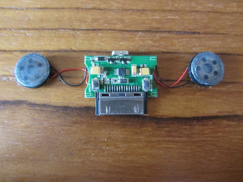
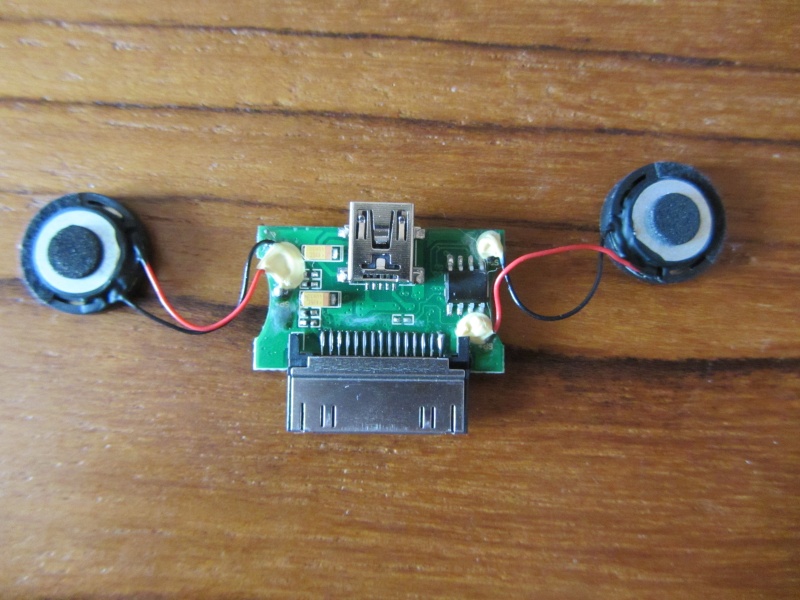
However, I want to do something easy before, like soldering the speakers. But I realized that mines are not exactly like on this tutorial can't find the ground ! Here's mine:

img_3111.jpg

img_3112.jpg


How can I find it, with my multimeter for exemple ?

[edit] WTF ? Why the link I putted send to a batman video ? :eek: So the url of the tutorial: http://www.made-by-bacteria.com/viewtop ... =179&t=732
[edit 2] Just type "bacteria mod amp" on google... :mrgreen:
 
Il faut mettre des trous dans ton moule aussi, au niveau des aretes. Et surtout chauffer plus le plastique.

Pour trouver la terre, sort ton multimetre, cherche un continuite entre le metal apparent de la prise et un autre point, ou entre un autre point et un des cables noirs. A mon avis tu trouvera la terre dans les coins, en gratant le vert pour reveler le doré qui fait contact
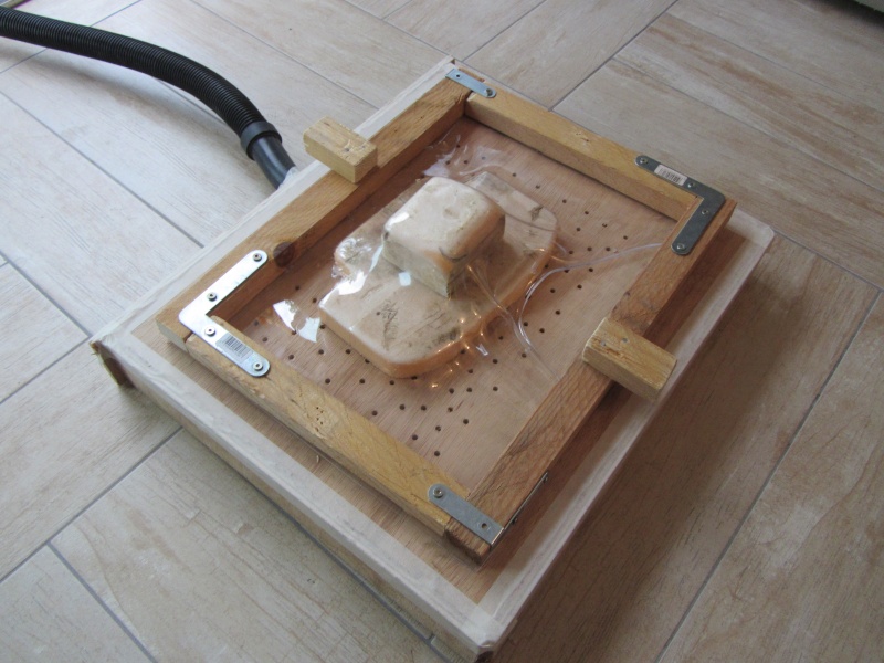
 
Ok ! Merci des conseils ;)

[edit]

Audio not working... don't know why :(
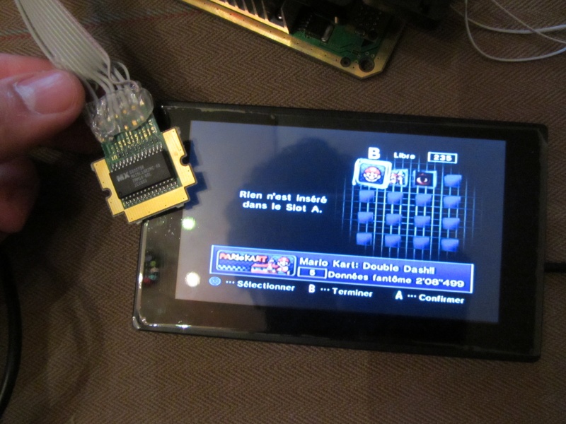
But I re-soldered the screen and changed the wires used for the regulator. It works, and here a picture with the memorycard relocation:

img_3113.jpg


:mrgreen:
 
Sorry for double posting, but my audio problem make me perplex... I tested with the multimeter the connectivity between the modo audio pins and the positive of each speaker, but the resistance is 1 (it seem to be not linked). The ground is ok, but I don't know what I have to check to know if it's broken or not...

[edit] @Uni: I don't know where it will go in the case, so long wires let me more possibilities to put it were I want than shorters.
 
Are you feeding it though an audio amp or just right to the speakers? You make it sound like it is right to the speakers.
 
I use an audio amp, but I don't know what I could test with the multimeter to know where the problem is. So I checked random points on the amp and on the mobo...
 
Hi, I'm back (I passed my final exams :mrgreen: ). It's time for me to continue working on my GCp !
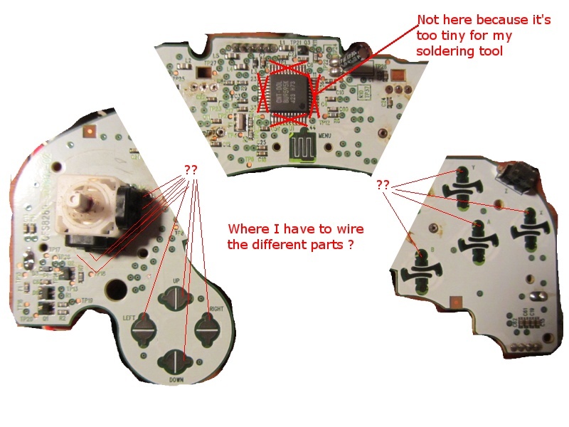
So, that I would like to do, it's to wire up the controller. I need to cut it in two, or tree parts, but I don't know how to do... I mean, I don't have the stuff to wire anything on the chip (too tiny), but I didn't found any schematics to see where I could link the two parts... A little picture to explain:

manett10.jpg


So... need help :confused:
 
Perfect !
[edit] Not exactly... I don't have the same model (I can see that all the hidden traces are not exactly the same), but I'll try with... How do you usually do with the controllers ?
 
Back
Top