mymixed
Well-Known Member
This is my second N64 portable, and I'm shooting for world's smallest. I'm taking everything I learned from my first portable and applying it to this portable. Also, no RCP wire. It will be smaller than the tri-sixty-force because it will have no spacer, however it is the same case (an SL-68p). Progress!
First off, the case:


Now, the board. What I did was solder through the outside holes, unlike most portables which solder on top of the holes or through the middle holes and drag soldered out. The reason for this was to solder that soldering to the outside holes will make it much stronger and it was much quicker to do. It worked on the first try! So how I did this was by tinning all of the board's outer connections and then using my desoldering iron to remove the solder. Once I had this done, I just soldered the IDE through the board and snipped it like I was soldering a kit! . This did not take very long to do. However, I could not remove some of the solder on the edge of the cart slot, so I did have to solder on top for that part. Anyway, pics:

I cleaned this off before I relocated:

Relocated:

The controller is pretty awesome , It has green ceramics! It's a super pad and on the back it says patent pending, so I think it was one of the first models! I'm going to cut this pretty small too. Pics:

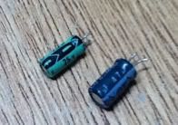
Teh Caps:

Here's the board in it's case. However, it will be cut a lot smaller than this:

Here's the mobo's side by side:

Update 1:
It will also have an expansion pack that is bent at a 90 degree angle. Anyone know how to do that? Also, i'm thinking of a name as we speak, so any help would be appreciated. Progress tomorrow!
- mymixed
First off, the case:


Now, the board. What I did was solder through the outside holes, unlike most portables which solder on top of the holes or through the middle holes and drag soldered out. The reason for this was to solder that soldering to the outside holes will make it much stronger and it was much quicker to do. It worked on the first try! So how I did this was by tinning all of the board's outer connections and then using my desoldering iron to remove the solder. Once I had this done, I just soldered the IDE through the board and snipped it like I was soldering a kit!

I cleaned this off before I relocated:

Relocated:

The controller is pretty awesome

Teh Caps:

Here's the board in it's case. However, it will be cut a lot smaller than this:

Here's the mobo's side by side:

Update 1:
It will also have an expansion pack that is bent at a 90 degree angle. Anyone know how to do that? Also, i'm thinking of a name as we speak, so any help would be appreciated. Progress tomorrow!
- mymixed


