OBDp, or On Board Diagnostics for Portables WIP

All my old junk is worthless. And people where I live buy insanely low and sell insanely high. Maybe I'll sell some of my games to the guy at the pawn shop. Including some of the ones I bought from him. :lol:

In any case, I'm probably going to build a DAPA cable, as soon as I can find the connector, I know it's here somewhere. Then I have to buy an ATMega168, but obviously I never order JUST what I need, shipping is too much for that. So I'll end up spending upwards of $50.
 
How's that going, XCVG? Need any help, just let me know.

I just paid for this:

http://cgi.ebay.com/2X-ATMEL-ATMEGA128- ... 1|294%3A50

That will give me two packages, I'll likely send one off to someone for free as a test unit/feedback kind of thing.

As an update, I've made a small amount of progress in figuring out the ADC functions. I've decided to create the PC-side software in VBe, (Visual Basic Express) for a variety of reasons. I've been working on the front end today, I'll post a pic of that later today, if I finish it out.
 
Oooh, that's cool. I didn't know they made ones like that! Anyway I haven't got to the DAPA cable yet, because I've been on vacation. Now I'm back so I'll get on it as soon as I find my connector. I have one somewhere... Anyway I've got to get a microcontroller, I'm going to deal with that soon.

Is your front-end going to have flashy graphics and pretty colours? :whistle:
 
I'm not really looking for flashy graphics right now, just something that's operational. Later on, I may spend some more time on the front end. As it stands right now, we've got some transparency and a basic menu system. Here's a pic:

obdp.jpg


Yes, the ModRetro logo will stay as the about page pic, and the icon will remain the same.
 
Thank you ;)

I don't see any reason why it won't work in Vista, but I am developing under an XP environment.
 
Okay, got the computer side of my DAPA cable done, but I haven't decided what to do with the other end. Should I just have loose wires? Use this 10-pin connector I have? Use headers (which I don't have)? Solder to a target board? Whatever, I'll figure it out if I ever get my other parts (I owe my parents $40 in addition to not having a lot of money right now).
 
I left the other end just as bare wires to plug into the breadboard; however, I would recommend doing a header setup, because it makes life so much easier. (Don't have to figure out the pin-out etc again and again with each setup.)

I'm re-doing mine, as I officially cannot write larger-sized programs; have too much noise in the process, and fails the write. Therefore, I need a shorter cable.
 
Wait, I thought you had a real programmer? Why are you using a DAPA cable? :huh:
 
I'm doing this 100% home-made so that I can take pictures and write a how-to as I go along; also, so I know that the target audience will have the same results as I am.
 
The package arrived intact from China today! I must say, I'm somewhat surprised it arrived so quickly; I was expecting another week.

In any case, here is the PCB itself:

dcp129.jpg


As you can see, it's quite thin, and not real long or wide. The chip itself is not that much thicker than the quarter (if not as thin or thinner. Haven't stacked them together yet LOL) So, quite small.

The holes you see there are where the header pins (supplied) are to be installed. They are small pitch, but no different than an N64 cart. I am taking a two-week vacation in two weeks, so we should have a good video and picture sequence on getting this put together.

Time to go leave some feedback on eBay.....
 
How nice of you to get the board made in China. Even homemade stuff is Chinese crap? I kid, I kid :rofl: . The price can't be beat!

Anyway, looks like it's coming along nicely. Is that some sort of adaptor board?
 
Yep, that's an adapter board, kind of like those transmitter boards you find in wireless controllers.

One thing of note, this thing does not have any solder pre-laid (not surprising, but still noteworthy.) This means that I'll have to go over some of the more in-depth techniques of SMT soldering, which isn't a whole lot of fun for the beginner electronic hobbyist - but, we'll git 'r' done.
 
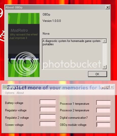
Ok, finally some progress. In the hope of making this project as user-friendly as possible, I attempt to find a means to solder this thing without the need for special materials or equipment. Unfortunately, due to the nature of the hardware, it's impossible without needing SOMETHING. But, I did manage to get this done using a 10 dollar Harbor Freight item! An adjustable-temp, adjustable-speed heat gun.

Materials required:
atmega128L
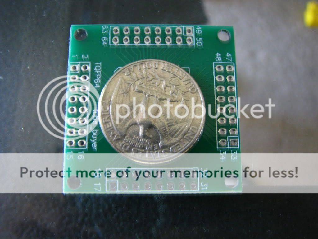
The PCB adapter board for the '128
Regular paste flux for ROSIN soldering
Soldering iron, preferably fine tip
Heat gun
Latex gloves
Tweezers
Mask

Instructions:
First, thoroughly cover the pads with flux - don't be shy, it's getting cleaned up after we're done anyway. Next, get your soldering iron and get a bead of solder on the end of the tip. Then, SLOWLY drag the tip along the pads. The solder will automatically flow from the tip to the pad, and shouldn't need much coaxing to get where it needs to be, if any. You will be burning flux as you do this, don't breathe it in. Use a fan or a mask.

Not a whole lot of solder is required; you'll be able to see the solder flow onto the pad, and what little you see is all you need. Once you've completed all four sets, you have an option: you can either use alcohol to clean the flux residue off, or you can use paper towels. The paper towel method has a benefit of leaving some sticky residue, which makes placement a pain in the rear BUT, has the added benefit of helping keep the processor in place. Either way, once you're done cleaning the residue off the board, find a suitable, HEAT RESISTANT base to place the PCB onto. I used my flat top stove.

Next, carefully place the processor onto the pads - NOTE THE POSITION OF PIN 1. It's not catastrophic if you solder the processor backwards, but the pin numberings will be wrong, and you will have to continually correct for the mistake. Once you have made sure all pins are lined up appropriately, get out the heat gun.

Turn the heat setting all the way up, and place the speed on high. Let it run for about 2 or 3 minutes so that it has plenty of time to heat up completely. Now, start about three feet above your PCB, and slowly move the gun downwards until you are about half an inch above the processor. If you've a steady arm and hand, you should not have a problem with the air from the gun moving the processor - the air flow should be DOWN at all times, but turbulence can cause problems. If the processor moves, reset the processor and try again.

Alternate between staying on the chip for 15 seconds, then removing heat for 15 seconds, then reapplying heat for 15. I repeated three times, and part was successfully soldered.
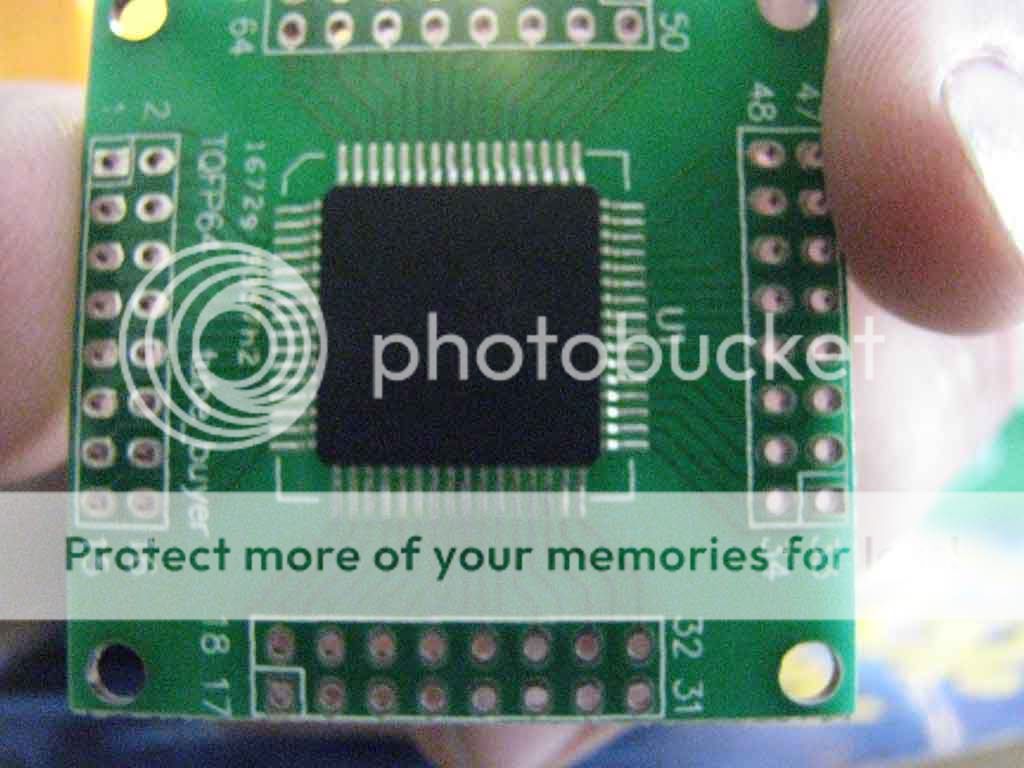
Here's the result:

soldered.jpg


It came out very clean, I was quite pleased with the results. I will be doing another PCB this evening, I will be making a video of that build, and will merge this reply with the original post.
 
Neeeet...

Would it be possible to hand solder it? I think it would be possible but require skill and it would be very tedious.

But what are the latex gloves for? :wtf:
 
This IS hand-soldering... after a fashion. I don't fancy having to tack each and every single pin on one of these, it'd be entirely too tedious, and completely unnecessary. A hot plate, toaster oven, or electric skillet can replace the hot air gun in this step. However, except for the toaster oven, these options can result in uneven results

The latex gloves are used for handling the microcontroller. Handling one without protection could cause ESD and fry the chip.
 
robm said:
This IS hand-soldering... after a fashion. I don't fancy having to tack each and every single pin on one of these, it'd be entirely too tedious, and completely unnecessary. A hot plate, toaster oven, or electric skillet can replace the hot air gun in this step. However, except for the toaster oven, these options can result in uneven results

So it's possible, but pointlessly tedious? Also, wouldn't it be better to simply ship these with the microcontroller already on, so no SMD soldering is necessary?

robm said:
The latex gloves are used for handling the microcontroller. Handling one without protection could cause ESD and fry the chip.

Latex isn't that good for anti-esd purposes. An anti-static wrist band is a lot better. If that's unavailible, touch the case of your computer before you do it.
 
I will be offering units pre-assembled for those who don't want to do this themselves, for members of ModRetro only, for cost of shipping. Otherwise, it's more expensive to buy a pre-assembled package online somewhere.

You are correct, latex gloves aren't fantastic themselves, but your fingers have other contaminants that just aren't good for electronics. Soldering these completely by hand would give me nightmares, but then, I can't see up-close anymore. (As a forthcoming video will show.) I won't say it's impossible, I will say it would be unnecessary.

Video compiling now, will send to youtube here shortly.
 
robm said:
I will be offering units pre-assembled for those who don't want to do this themselves, for members of ModRetro only, for cost of shipping.

Plus the cost of parts, I assume? Or maybe you really are nice enough to buy the parts for us too... ;)

I cannot wait for this to be done, it is awesome! I think I mentioned it in the chatroom, but you seriously stand to make some dough selling these to the high power hobby laser scene. They are willing to spend $30+ on a simple current regulator, if they had a system for monitoring heat levels on the heatsink, current going to the laser, and stuff like that, they would absolutely be falling over themselves to give you money. :lol:
 
Should have clarified, cost of shipping AND parts LOL. I will say I will have one extra unit to give away at the end of the project; I've got two of these made now, I'm not going to need both.

I can't wait until I've got this done either; it's showing some promise, and the uses this has outside of portables is just about endless. How hot do those "hobby lasers" get, Palmer?

Here's the vid for hot air reflow!


Edit: Youtube embedding not working... might be because it isn't done processing yet. Link: http://www.youtube.com/watch?v=yhhLyxkTVQI
 
Back
Top