Summary:
This project is intended to provide a passive diagnostic system for any electrical component that may benefit from an ob-board diagnostic system to ease troubleshooting, cutting down on the need for opening the case and manually checking things like voltage, operation evident from target system's processor, and other information. The project will remain open-source, despite obvious uses outside of portables. This includes both hardware and software.
Target-system-side hardware shall consist of a simple circuit consisting of a single processor, the atmega128, which shall communicate to a PC through a USB port. I am unclear in this portion of design whether or not the project shall utilize the LOB64 port, a popular form of connecting two (or more) N64 portables together, or will utilize a mini-USB port instead. For ease of migration across systems, I am leaning towards the mini-USB port solution.
Receiving-side software shall consist of a simple, utilitarian user interface that displays simple, quickly-accessible information with little to no bells or whistles. I do plan on implementing a firmware update feature, as it cannot be expected that everyone in the field are able to flash their own microcontrollers in the event of future device upgrades.
Overview of capability of device:
The "brain" of the project, the Atmega128L, is an over-powerful device for this application. It is a 8 MHZ RISC processor capable of almost one million instructions per second per 1MHZ clock speed. However, the processor's power requirement is extremely low - it can operate at voltages between ~2.5v to about 5.5v, making power supply for the device a simple matter for most portables. For instance, the N64 projects require a 3.3v source - well within the processor's requirement, and the power source is typically drawn from a very reliable power source. Amperage draw is basically negligible.
The '128 has eight ADC lines, meaning there are eight possible voltages that the device can sample and turn into a digital signal that can then be communicated through the link. This capacity is really only a small fraction of the device's capabilities, thus the potential for future expansion. The '128 is more than capable of running popular serial LCDs, allowing the development of a hand-held diagnostic "reader" instead of requiring a PC, as an example. A small LCD could be installed in the case of the target system as a means for the AVR to communicate without the need for a link at all. These expansions are not within the scope of this project.
Current project goals/progress:
Design target device circuit
Design PC utility front-end (Easiest step of the project. 50% done, diagnostic link development to proceed)
Begin development for '128 firmware
Develop solution for communication between target device and PC. (Additional hardware required between '128 and PC?)
Feature requests are welcome")
Current feature requests:
Mini-USB port connectivity
Means of determining if N64 cart is wired correctly
Instructions for building programming cable
DISCLAIMER: THIS SECTION COULD CAUSE YOUR COMPUTER TO EXPLODE, RENDERING YOUR PARALLEL PORT USELESS, YOUR DOG WILL LEAVE YOU, AND YOUR WIFE WILL TAKE THE KEYS TO YOUR JOHN DEERE. As a result, I cannot claim responsibility for any damage resultant from this guide.
This section is only for those who will want to program their own chips for this project, as I will be offering pre-flashed units due to the fact that not everyone will have the means to do this themselves.
I would like to give credit to the author of the Instructables article "Ghetto Programming:Getting started with AVR microprocessors on the cheap," by The Real Elliot, and http://www.captain.at for providing the pinout for the parallel port pinout.
Before we get started, I would like to make mention of a few things. For one, do not follow the Instructables article for this project, aside from the manufacture of the DAPA cable, particularly if you do not have a membership there, because you will not be able to download the applicable files for that specific project. Also, this project will call for requirements that aren't necessary for this project's final product, but as a prerequisite for those wishing to do their own flashing for the first time. For instance, you will need a breadboard, though obviously this will not be going into your portable.
This section is designed for those who have never flashed a microprocessor before in their lives, hence the reason for the guide on the creation of a DAPA cable, and the requirement that a standard chip be flashed FIRST. However, this does provide the opportunity for someone to use a less expensive alternative to the project's intended processor, the '168 over the '128, if the chip isn't fried in their first attempt (unlikely, but it happens.) This step will increase the initial investment in the diagnostic project, but will provide excellent opportunities later on for microprocessor development, so it is a great initial investment. For those of you who have done processor flashing before, you may skip this step entirely.
This guide does assume at least some electronics knowledge, so if there are gaps and you need help, please ask a question.
[links to required items forthcoming]
Items required:
Breadboard from Radioshack
atmega168
7805 voltage regulator
Hook-up wire kit (Radioshack,) would recommend 20 gauge
LED
25-pin MALE D-Sub connector with solder-type terminals (Radioshack)
Solder
Soldering iron
A 25 pin parallel port available on your desktop IMPORTANT
Assorted color wires, 1 foot to 2 feet long max
Some form of power for the breadboard, four AA's will be fine, or a wall-wart (AC-DC power adapter capable of at least 1.5a)
Multimeter
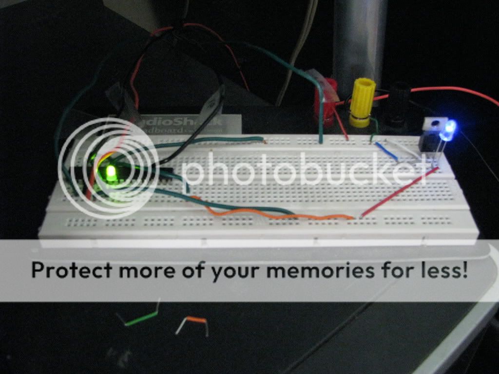
Refer to this image: http://i268.photobucket.com/albums/jj22 ... dcp098.jpg
You will see your basic components on this breadboard: the voltage regulator, the atmega168, hook-up wire, and an LED. If none of this makes sense to you so far, that's ok! Familiarize yourself with the breadboard, how easy it is to insert wires/etc, and come back when you're comfortable putting things into those small holes.
First, place your voltage regulator as shown in the picture. (The blue LED shown isn't required.) Looking at the regulator, your pinout is I-G-O, or igo as a mnemonic. That stands for Input-Ground-Output. (Collector, base, and emitter, if it pleases you.) Run wires from your power source to the red and black terminals of the breadboard, and run a jumper wire from your hook up wire kit from those terminals to the top two rows of the breadboard, one from the red post to a hole in the top row, and one wire from the black post to the second row at the top. Then, run a wire from the top row to a hole in-line with the input terminal of the regulator. Next, run a wire from the ground (second row at the top of the breadboard) to the, you guessed it, ground terminal of the regulator. Now insert a wire into a hole in the O, or output, row, leaving the other end free.
Now, connect your power source, and using the 20v DC (looks something like V-- on the dial) scale, measure the voltage at the end of the free wire. If it measures somewhere in the neighborhood of 5v, then you've done everything right so far! If it is ABOVE 5.2v, STOP - something is wrong, and this guide will not cover the required steps to compensate. Check all your wiring, and replace the regulator. A little under 5v is ok.
Now it's time for the fun part. Disconnect your power source, and refer to this image: http://www.sparkfun.com/commerce/images ... Pinout.jpg (Courtesy of Sparkfun.) Notice the notch at the top of the chip; your chip will have that same notch. Insert your atmega168 as shown in the picture provided above, making sure it straddles the groove running down the middle of the board and the notch of the chip points towards the reglator. That image is the pinout for the atmega168. For our purposes, Vcc and AVcc connect to the same power source - the output from the voltage regulator. Connect those two pins to output, using the breadboard example shown above as reference. These pins are 7 and 20. Next, connect pins 8 and 22 to ground.
Finally, insert your LED between pins 23 and 22. 22 is GND, so make sure that the SHORTER lead of the LED is inserted into that row.
Now it's time to build your cable. Refer to this link: http://www.instructables.com/id/EXIM2VJJ51EUKIKWDF/
That is a link to a picture of the cable we are making. The D-Sub connector you bought from Radioshack should look just like the one pictured. If not, return it now and get the right one!
Now, make 5 lengths of wire between a foot and two feet in length, no longer. The reason for this is that the longer the wire is, the more noise will interfere with the signal while the PC is programming the chip - the shorter, the better, as long as it'll reach your breadboard with no problems!
On the reverse of the connector, you will notice that the pins are numbered, the top-right pin (FACING THE SOLDER SIDE) is pin 1, the lower-left pin (FACING THE SOLDER SIDE!!!!) is pin 25. This is the pinout for soldering purposes: (Ignore the jargon for now, just solder wires to the appropriate pins)
Pin 1 - SCK
Pin 2 - MOSI
Pin 11 - MISO
Pin 16 - RESET
Pin 18 - GND
Once you have those wires soldered to the connecter, you're done with the cable! Try to make sure each wire is a different color, if possible, and make note of which one is which. Wrapping tape around the wire and writing on it works too.
Refer to the atmega168 pinout. Connect each wire from the cable to its corresponding pin on the processor. In our case:
SCK is connected to pin 19
MOSI is connected to pin 17
MISO is connected to pin 18
RESET is connected to pin 1
GND is connected to pin 8 (or any GND really)
Next, plug your cable into the parallel port of your computer. i can haz blinky light nao?
No, we're not ready to program the chip yet! Now it's time to set up the required software. You can download WinAVR here: http://sourceforge.net/projects/winavr Now, you're almost there. Almost. Once installed, navigate to the directory /winavr/bin, and execute the batch file install_giveio, which enables the parallel port.
Once completed, download this file: http://novaftp.itrello.com/Rob%20Morrow ... stdapa.zip That archive contains the makefile, the source, and hex file for our first blinking LED project. You have two options at this point - you can go ahead and proceed to compile the code yourself, or you can go straight to flashing the chip. If you wish to compile the code yourself, navigate to the winavr/pn directory, and run the program pn.exe, (programmer's notepad.) Make sure all of these files are in the same directory: make, firstdapa.c, io.h and delay.h. Open firstdapa.c using programmer's notepad. Near the top of the program you will see these two lines:
You may have to edit these two lines to reflect the actual path that those two files are in. For instance:
Once you have done this, go to Tools -> [WinAVR] Make All. This will compile the program into a file titled firstdapa.hex. This is the actual machine code to be flashed to the microcontroller. If you see an error in the dialog box at the bottom that says "io.h" or "delay.h" not found, make sure the path in the program is correct.
Verify that firstdapa.hex was created; if so, we are ready to flash the chip!
Next, open a shell window (Start -> Run -> cmd.exe), navigate to WinAVR/bin, and type in this line:
avrdude -p atmega168 -P lpt1 -c dapa -e reset -U flash:w:firstdapa.hex
Where firstdapa.hex should be the full path of where your firstdapa.hex file is located.
Once you hit enter, avrdude will initialize the chip, write the file to the chip, and verify the result. Here is what you need to watch for: if your cable was too long, or if there is a bad connection somewhere, you may end up with a verification error and errors regarding fuses. If this happens, hit "n" for each fuse it asks to reset, otherwise if you hit "y" the program will hang and you'll need to reprogram the chip. However, if everything went well, the LED on the chip should start flashing immediately!
If the program failed, double-check your breadboard to ensure all connections are properly inserted, check your pinouts, and make sure that you did run install_giveio (if avrdude reported an error accessing the port.)
Bask in the glow of your blinking LED. It's ok. It loves you too.
This guide was to ensure two things: 1) That the user can, in fact, program a chip using their PC, and 2) The user successfully flashed a chip before programming the atmega128. The '168 can be used for this project, however, so if the chip survived its first manipulation by a microcontroller newbie, then the purchase of the '128 will be unnecessary. This same procedure applies for programming the '128, so if you can do this, you can do the '128!
This project is intended to provide a passive diagnostic system for any electrical component that may benefit from an ob-board diagnostic system to ease troubleshooting, cutting down on the need for opening the case and manually checking things like voltage, operation evident from target system's processor, and other information. The project will remain open-source, despite obvious uses outside of portables. This includes both hardware and software.
Target-system-side hardware shall consist of a simple circuit consisting of a single processor, the atmega128, which shall communicate to a PC through a USB port. I am unclear in this portion of design whether or not the project shall utilize the LOB64 port, a popular form of connecting two (or more) N64 portables together, or will utilize a mini-USB port instead. For ease of migration across systems, I am leaning towards the mini-USB port solution.
Receiving-side software shall consist of a simple, utilitarian user interface that displays simple, quickly-accessible information with little to no bells or whistles. I do plan on implementing a firmware update feature, as it cannot be expected that everyone in the field are able to flash their own microcontrollers in the event of future device upgrades.
Overview of capability of device:
The "brain" of the project, the Atmega128L, is an over-powerful device for this application. It is a 8 MHZ RISC processor capable of almost one million instructions per second per 1MHZ clock speed. However, the processor's power requirement is extremely low - it can operate at voltages between ~2.5v to about 5.5v, making power supply for the device a simple matter for most portables. For instance, the N64 projects require a 3.3v source - well within the processor's requirement, and the power source is typically drawn from a very reliable power source. Amperage draw is basically negligible.
The '128 has eight ADC lines, meaning there are eight possible voltages that the device can sample and turn into a digital signal that can then be communicated through the link. This capacity is really only a small fraction of the device's capabilities, thus the potential for future expansion. The '128 is more than capable of running popular serial LCDs, allowing the development of a hand-held diagnostic "reader" instead of requiring a PC, as an example. A small LCD could be installed in the case of the target system as a means for the AVR to communicate without the need for a link at all. These expansions are not within the scope of this project.
Current project goals/progress:
Design target device circuit
Design PC utility front-end (Easiest step of the project. 50% done, diagnostic link development to proceed)
Begin development for '128 firmware
Develop solution for communication between target device and PC. (Additional hardware required between '128 and PC?)
Feature requests are welcome
Current feature requests:
Mini-USB port connectivity
Means of determining if N64 cart is wired correctly
Instructions for building programming cable
DISCLAIMER: THIS SECTION COULD CAUSE YOUR COMPUTER TO EXPLODE, RENDERING YOUR PARALLEL PORT USELESS, YOUR DOG WILL LEAVE YOU, AND YOUR WIFE WILL TAKE THE KEYS TO YOUR JOHN DEERE. As a result, I cannot claim responsibility for any damage resultant from this guide.
This section is only for those who will want to program their own chips for this project, as I will be offering pre-flashed units due to the fact that not everyone will have the means to do this themselves.
I would like to give credit to the author of the Instructables article "Ghetto Programming:Getting started with AVR microprocessors on the cheap," by The Real Elliot, and http://www.captain.at for providing the pinout for the parallel port pinout.
Before we get started, I would like to make mention of a few things. For one, do not follow the Instructables article for this project, aside from the manufacture of the DAPA cable, particularly if you do not have a membership there, because you will not be able to download the applicable files for that specific project. Also, this project will call for requirements that aren't necessary for this project's final product, but as a prerequisite for those wishing to do their own flashing for the first time. For instance, you will need a breadboard, though obviously this will not be going into your portable.
This section is designed for those who have never flashed a microprocessor before in their lives, hence the reason for the guide on the creation of a DAPA cable, and the requirement that a standard chip be flashed FIRST. However, this does provide the opportunity for someone to use a less expensive alternative to the project's intended processor, the '168 over the '128, if the chip isn't fried in their first attempt (unlikely, but it happens.) This step will increase the initial investment in the diagnostic project, but will provide excellent opportunities later on for microprocessor development, so it is a great initial investment. For those of you who have done processor flashing before, you may skip this step entirely.
This guide does assume at least some electronics knowledge, so if there are gaps and you need help, please ask a question.
[links to required items forthcoming]
Items required:
Breadboard from Radioshack
atmega168
7805 voltage regulator
Hook-up wire kit (Radioshack,) would recommend 20 gauge
LED
25-pin MALE D-Sub connector with solder-type terminals (Radioshack)
Solder
Soldering iron
A 25 pin parallel port available on your desktop IMPORTANT
Assorted color wires, 1 foot to 2 feet long max
Some form of power for the breadboard, four AA's will be fine, or a wall-wart (AC-DC power adapter capable of at least 1.5a)
Multimeter
Refer to this image: http://i268.photobucket.com/albums/jj22 ... dcp098.jpg
You will see your basic components on this breadboard: the voltage regulator, the atmega168, hook-up wire, and an LED. If none of this makes sense to you so far, that's ok! Familiarize yourself with the breadboard, how easy it is to insert wires/etc, and come back when you're comfortable putting things into those small holes.
First, place your voltage regulator as shown in the picture. (The blue LED shown isn't required.) Looking at the regulator, your pinout is I-G-O, or igo as a mnemonic. That stands for Input-Ground-Output. (Collector, base, and emitter, if it pleases you.) Run wires from your power source to the red and black terminals of the breadboard, and run a jumper wire from your hook up wire kit from those terminals to the top two rows of the breadboard, one from the red post to a hole in the top row, and one wire from the black post to the second row at the top. Then, run a wire from the top row to a hole in-line with the input terminal of the regulator. Next, run a wire from the ground (second row at the top of the breadboard) to the, you guessed it, ground terminal of the regulator. Now insert a wire into a hole in the O, or output, row, leaving the other end free.
Now, connect your power source, and using the 20v DC (looks something like V-- on the dial) scale, measure the voltage at the end of the free wire. If it measures somewhere in the neighborhood of 5v, then you've done everything right so far! If it is ABOVE 5.2v, STOP - something is wrong, and this guide will not cover the required steps to compensate. Check all your wiring, and replace the regulator. A little under 5v is ok.
Now it's time for the fun part. Disconnect your power source, and refer to this image: http://www.sparkfun.com/commerce/images ... Pinout.jpg (Courtesy of Sparkfun.) Notice the notch at the top of the chip; your chip will have that same notch. Insert your atmega168 as shown in the picture provided above, making sure it straddles the groove running down the middle of the board and the notch of the chip points towards the reglator. That image is the pinout for the atmega168. For our purposes, Vcc and AVcc connect to the same power source - the output from the voltage regulator. Connect those two pins to output, using the breadboard example shown above as reference. These pins are 7 and 20. Next, connect pins 8 and 22 to ground.
Finally, insert your LED between pins 23 and 22. 22 is GND, so make sure that the SHORTER lead of the LED is inserted into that row.
Now it's time to build your cable. Refer to this link: http://www.instructables.com/id/EXIM2VJJ51EUKIKWDF/
That is a link to a picture of the cable we are making. The D-Sub connector you bought from Radioshack should look just like the one pictured. If not, return it now and get the right one!
Now, make 5 lengths of wire between a foot and two feet in length, no longer. The reason for this is that the longer the wire is, the more noise will interfere with the signal while the PC is programming the chip - the shorter, the better, as long as it'll reach your breadboard with no problems!
On the reverse of the connector, you will notice that the pins are numbered, the top-right pin (FACING THE SOLDER SIDE) is pin 1, the lower-left pin (FACING THE SOLDER SIDE!!!!) is pin 25. This is the pinout for soldering purposes: (Ignore the jargon for now, just solder wires to the appropriate pins)
Pin 1 - SCK
Pin 2 - MOSI
Pin 11 - MISO
Pin 16 - RESET
Pin 18 - GND
Once you have those wires soldered to the connecter, you're done with the cable! Try to make sure each wire is a different color, if possible, and make note of which one is which. Wrapping tape around the wire and writing on it works too.
Refer to the atmega168 pinout. Connect each wire from the cable to its corresponding pin on the processor. In our case:
SCK is connected to pin 19
MOSI is connected to pin 17
MISO is connected to pin 18
RESET is connected to pin 1
GND is connected to pin 8 (or any GND really)
Next, plug your cable into the parallel port of your computer. i can haz blinky light nao?
No, we're not ready to program the chip yet! Now it's time to set up the required software. You can download WinAVR here: http://sourceforge.net/projects/winavr Now, you're almost there. Almost. Once installed, navigate to the directory /winavr/bin, and execute the batch file install_giveio, which enables the parallel port.
Once completed, download this file: http://novaftp.itrello.com/Rob%20Morrow ... stdapa.zip That archive contains the makefile, the source, and hex file for our first blinking LED project. You have two options at this point - you can go ahead and proceed to compile the code yourself, or you can go straight to flashing the chip. If you wish to compile the code yourself, navigate to the winavr/pn directory, and run the program pn.exe, (programmer's notepad.) Make sure all of these files are in the same directory: make, firstdapa.c, io.h and delay.h. Open firstdapa.c using programmer's notepad. Near the top of the program you will see these two lines:
Code:
#include <io.h>
#include <delay.h>
You may have to edit these two lines to reflect the actual path that those two files are in. For instance:
Code:
#include <c:\program files\WinAVR\avr\include\avr\io.h>
#include <c:\program files\WinAVR\avr\include\avr\delay.h>
Once you have done this, go to Tools -> [WinAVR] Make All. This will compile the program into a file titled firstdapa.hex. This is the actual machine code to be flashed to the microcontroller. If you see an error in the dialog box at the bottom that says "io.h" or "delay.h" not found, make sure the path in the program is correct.
Verify that firstdapa.hex was created; if so, we are ready to flash the chip!
Next, open a shell window (Start -> Run -> cmd.exe), navigate to WinAVR/bin, and type in this line:
avrdude -p atmega168 -P lpt1 -c dapa -e reset -U flash:w:firstdapa.hex
Where firstdapa.hex should be the full path of where your firstdapa.hex file is located.
Once you hit enter, avrdude will initialize the chip, write the file to the chip, and verify the result. Here is what you need to watch for: if your cable was too long, or if there is a bad connection somewhere, you may end up with a verification error and errors regarding fuses. If this happens, hit "n" for each fuse it asks to reset, otherwise if you hit "y" the program will hang and you'll need to reprogram the chip. However, if everything went well, the LED on the chip should start flashing immediately!
If the program failed, double-check your breadboard to ensure all connections are properly inserted, check your pinouts, and make sure that you did run install_giveio (if avrdude reported an error accessing the port.)
Bask in the glow of your blinking LED. It's ok. It loves you too.
This guide was to ensure two things: 1) That the user can, in fact, program a chip using their PC, and 2) The user successfully flashed a chip before programming the atmega128. The '168 can be used for this project, however, so if the chip survived its first manipulation by a microcontroller newbie, then the purchase of the '128 will be unnecessary. This same procedure applies for programming the '128, so if you can do this, you can do the '128!