Nikoil

Member
NGCP

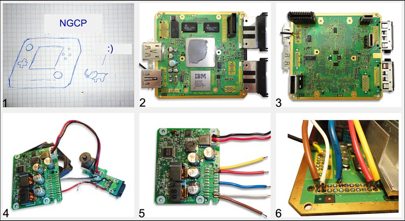
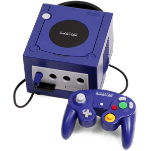
Many year ago when i was in school every week i watched Xplay tv show. Xplay make review on top best gamecube game. When it was i has only dandy. Then I think it best console in world. I very much wanted to get her for Christmas but..... And now after 10 year when i find this forum and learned about GC mod chip and how many peoples make portable console I decided to make a pocket version of the NGCPocket.


24353091844_2a7b205c92_o.png
 
Re: NGCP by Nikoil

I'll start with pictures. The cube should be a small and the first thing that comes to mind - likea elephant))

When I started I was nothing: cube, gamepad, memcard, display, buttons, triggers, mod mod chip etc. Almost all parts ordered from different countries, in my country gc - rarity.
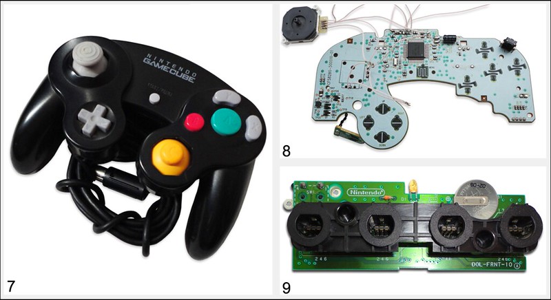
Today I received my console and already break it. Dimensions motherboard 11,9x12,6Sm (Pic 2,3) I ordered a small 3.5-inch display, controller, tact switches and another parts. Having dealt with the power supply. It is possible to remove the 12v supply line, and replace them on the five volts. We save 1 wire and plenty of space. The power board will be beyond the console.

25581310845_c73a5508b1_c.jpg


Disassembled joystick (pic 7-8) and controller board (pic 9). I will be use 3ds stick. Plastic case, controller board - no more needed.

24632121919_10ea149858_c.jpg
 
Last edited:
Re: NGCP by Nikoil

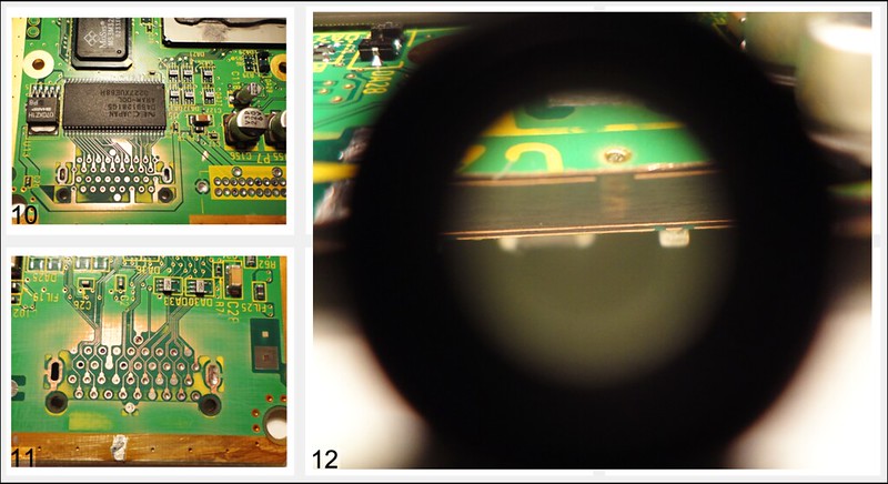
Started working with the motherboard. No schemes and datasheet - too bad! Pcb has 4 layers and thickness - 2mm. Need make power line map and delete many components . Photos 10-11 Handy X-rays.)

24705111540_f8438d4a7d_c.jpg
 
Last edited:
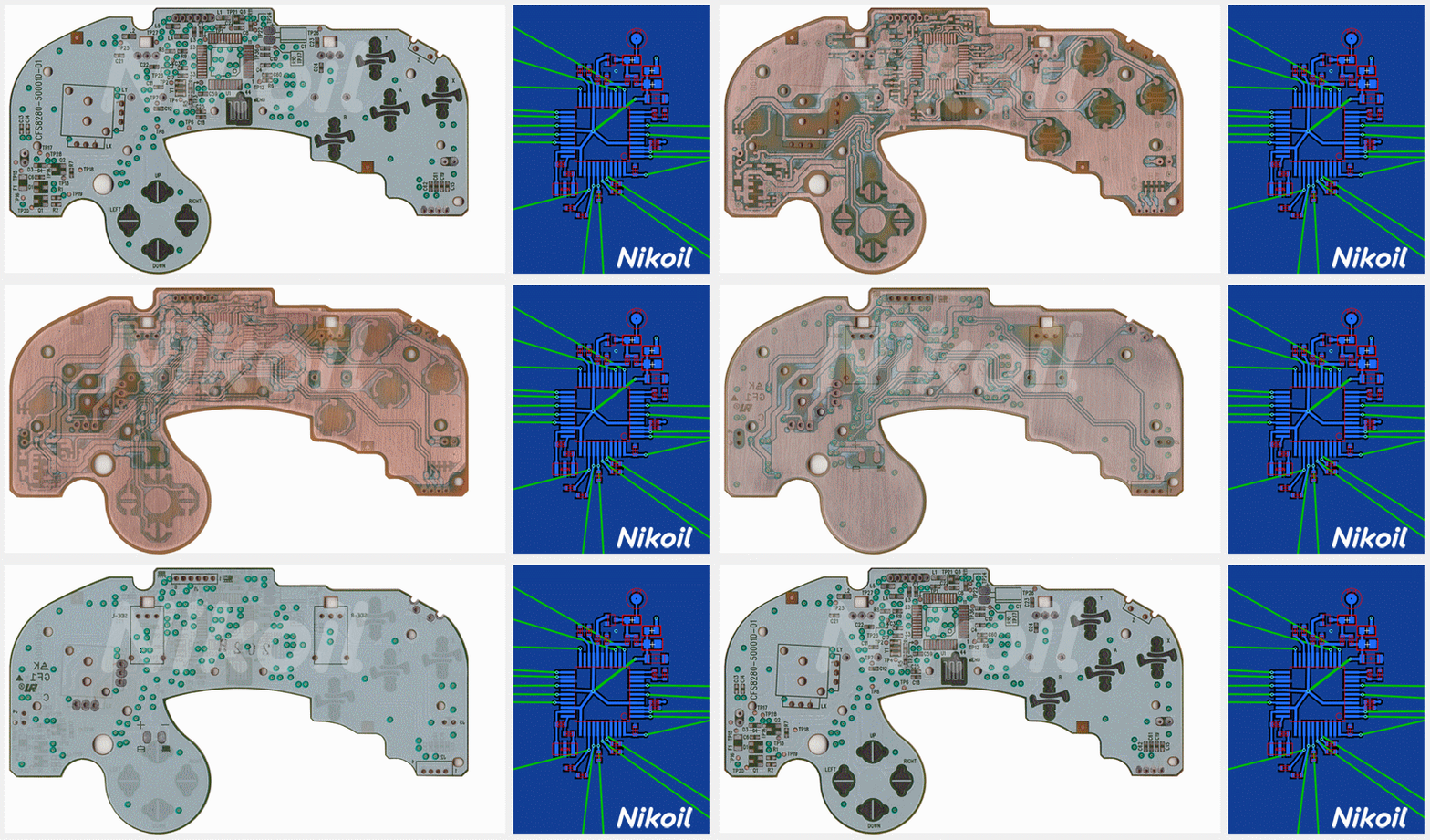
There are some (if they still exist) board scans that have been sanded that would probably help you since there aren't any datasheets.
 
Noah - Thank You! I know. I seen topik without soldering mask on board (really useful - he made big work) . A little bit later i publish what a scheme i use for my project: dc scheme, transparent overlay, cutting and pinout.
 
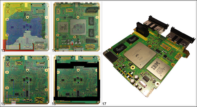
On (pic.13) remapping supply lines, transparent overlay for making the necessary circuits (pic.14). (Pic.15) pinout picture. Pic.16 is a cutting board line. The last photo of my motherboard after partial cutting. There were problems with the board after cutting, 5v line was in short circuit , and all because I was too lazy and not accurate :awesome:

24565519763_023010a1d6_c.jpg
 
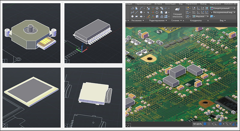
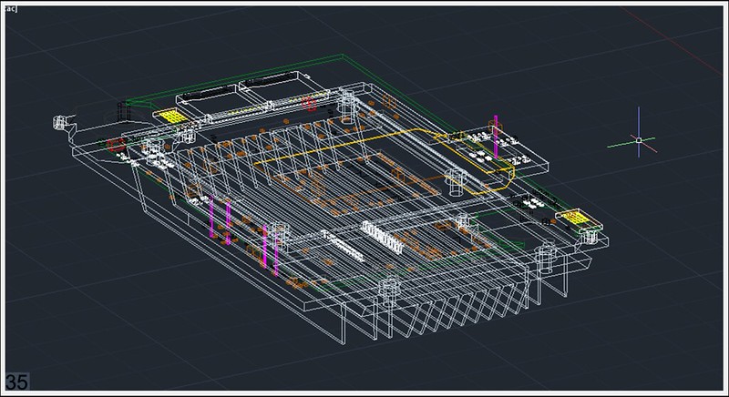
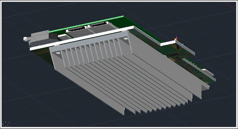
In AutoCAD I started modeling accessories and components. Attach a photo 3ds joystick (Pic 19), memory card, display, motherboard - 90% of the components.

25220840055_f1fffd2151_c.jpg


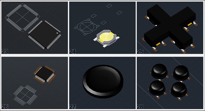
Few details: joysticks cpu, many buttons, wasp key cpu

25158774619_1518052788_c.jpg


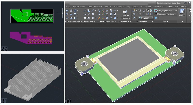
(pic30) main board prototype - v1

25500887996_65bf74cb6a_c.jpg


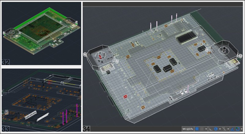
Continued. Expected thickness between the motherboard and prototype board - 3mm)

25232127540_3e9edf3c0a_c.jpg


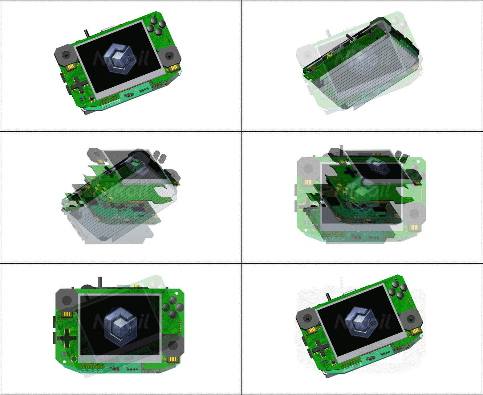
all together v3

25160843079_ef33cfb142_c.jpg


25435628481_679ab31d3b_c.jpg


And v24 model

25995309034_c1101bdacb_o.gif
 
Last edited:
Those are some sexy scans and models.

WAIT

WTF

THOSE ARE *Can'tSayThisOnTV*ING GIFS?

HOLY *Can'tSayThisOnTV* MAN.

You're my hero. <3
 
Components

Wasp Fusion

I connect modchip - working good!

25895167300_610ed5685e_c.jpg


Now does not work)

26101670871_eb7b311c76_c.jpg


3.5" TFT LCD

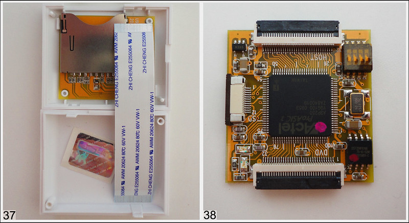
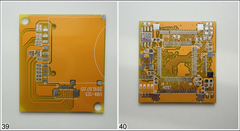
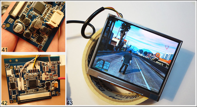
I buy 3.5 inch display. I was surprised by his quality. For him test i connect xbox 360 and run gta 5 for 3.5 inch its beautiful. Small pcb on T118 chip, he can work on 480i has av input, svideo input, tv input and another cool hiden opportunity for future upgrades. Lcd - i shocked, so bright so juicy. My camera cant make real color this lcd - hi so bright and camera can't focus on him. Quality better then crt tv on this monitor i can read text! For lcd need 12v but if unsolder step down controller BM1410 (pic.41) and his parts we can use it with 5v. Electrolytic capacitor i change to tantalum capacitor. Quartz and inductor replaced, now he smd type (pic.42)

26075561032_3c6924655f_c.jpg


Memory Card

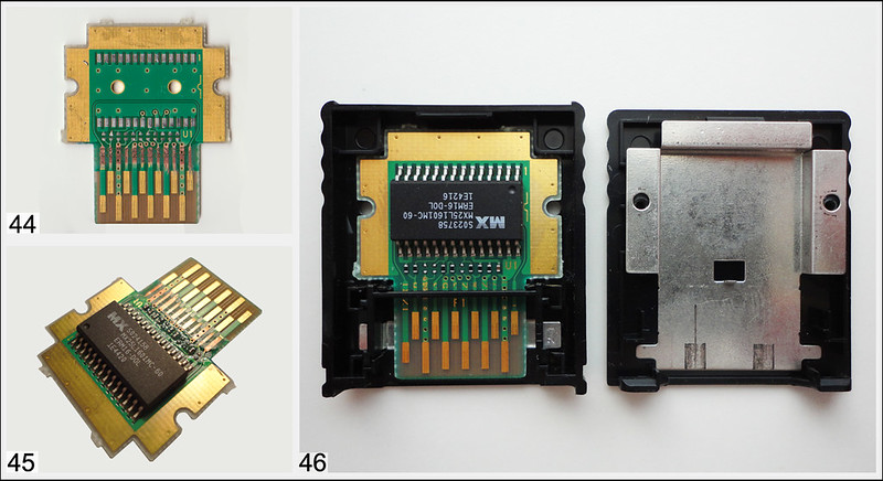
Memcard. I buy 2pc on Ebay. From Japan,) original, was) like new!

26142070146_ec1b295c6c_c.jpg


Another parts

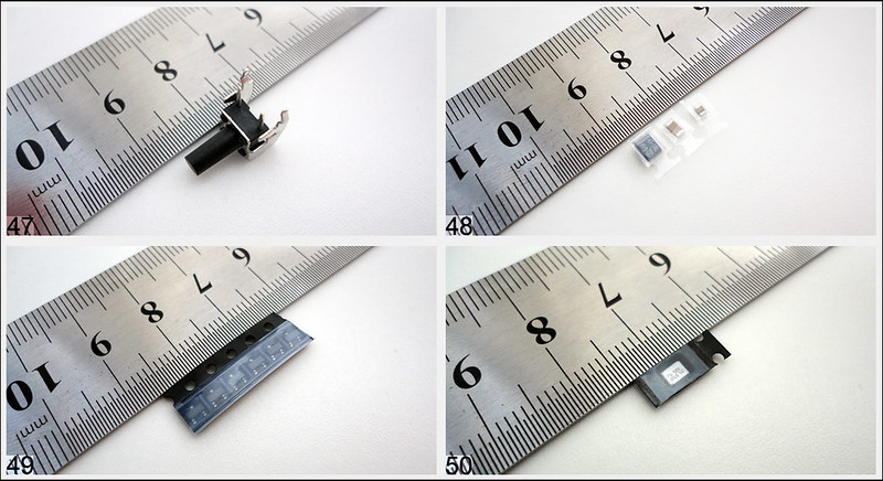
Z-button (pic.47), capacitors, transistor for triggers trick on pic.49 (soon!), new small quartz for tv module.

25563843834_d6772009f0_c.jpg


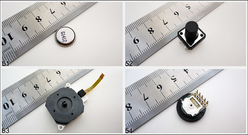
New small battery for bios, buttons for A B X Y on pic.52 (for button trick soon), joystick and potentiometer for amp.

26102264301_282be1e62c_c.jpg


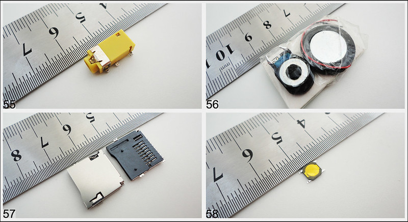
Av output, speakers, microsd card slot for wasp and SD Gecko, smd buttons for button trick will be use on d-pad, start button and A B X Y.

26102264111_47d0b893f2_c.jpg


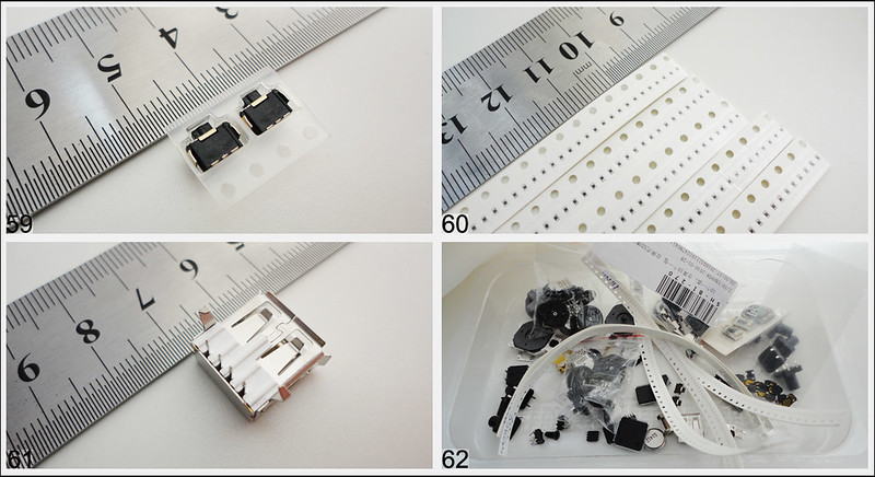
Nokia camera button for trigger, many smd 0402, usb and all together.

26326441340_bc445e71af_c.jpg


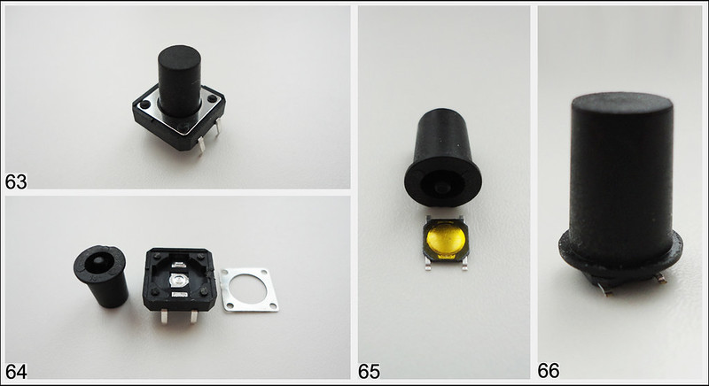
Smd buttons idea pic.63-66

26573658056_6834830380_c.jpg


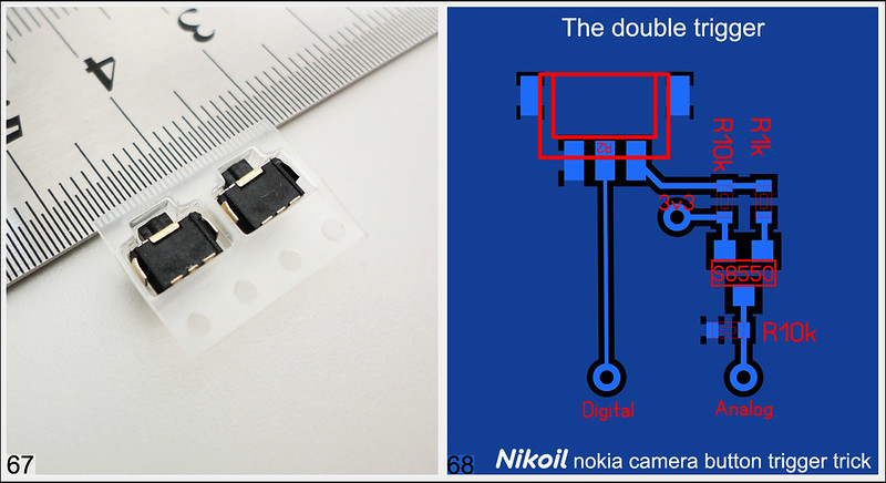
And trigger trick with nokia 2 click camera button for trigger + scheme
32075927064_016ca814b4_c.jpg
 
Last edited:
Main PCB

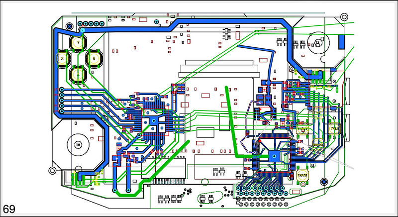
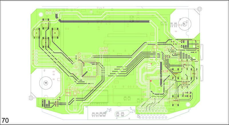
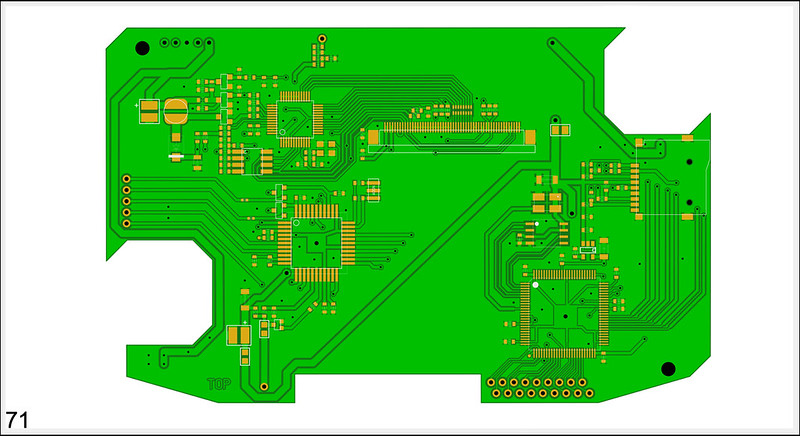
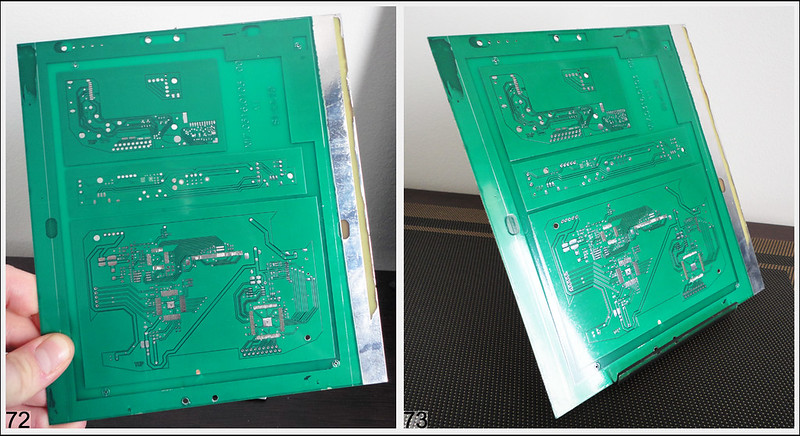
I make this scheme 2 weeks and when i finished i very want pcb factory quality and i get it + ~3 weeks
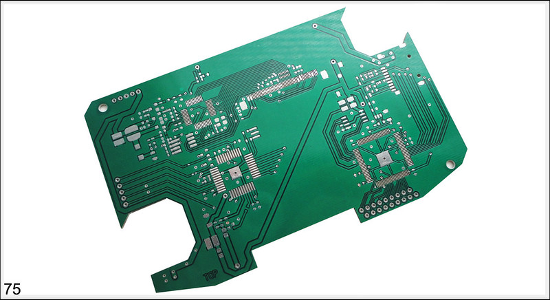
In process

26508227752_721679c13b_c.jpg


Scheme on 3d model
26508227452_de4a8ee007_c.jpg


Photo view

26575255576_db0160d8c1_c.jpg


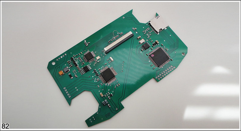
My babe

26328318970_25b2fbc066_c.jpg


26536033861_b87b3c1573_c.jpg


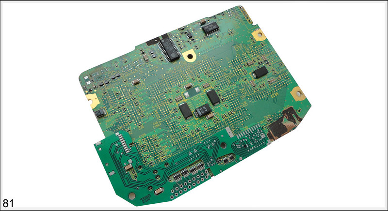
Pcb after cutting


25998657103_5e0612c0a0_c.jpg


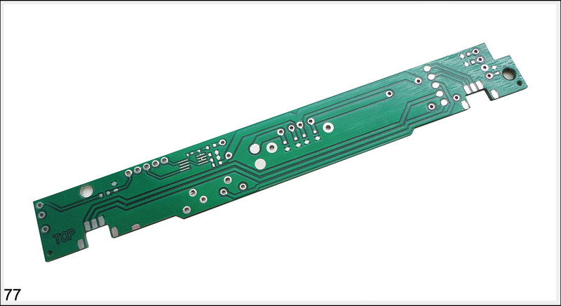
Dc supply board

25998845813_370350cbc3_c.jpg


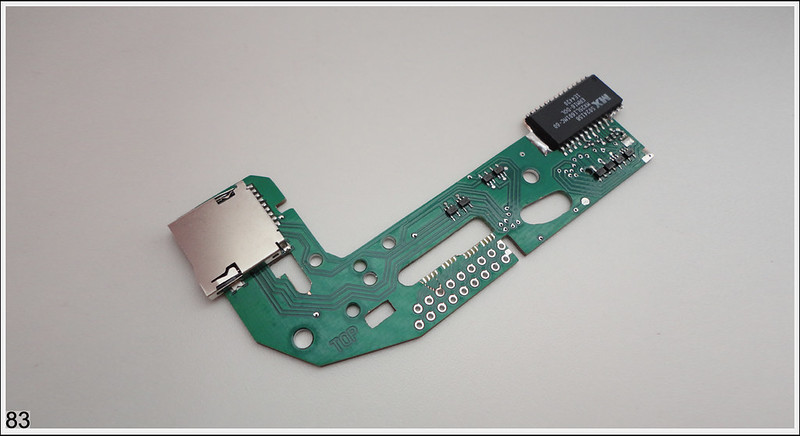
Trigger and sound board

26575918066_07f4051760_c.jpg


Wasp fusion, memcard and sd gecko board

25996625924_1a80f10b2d_c.jpg


Dimensions check

25996976444_183de1819b_c.jpg


Final cutting GCP board with panel together

26509293432_2d8d2cc4f3_c.jpg


After >200 components

26576413636_9435e3712c_c.jpg


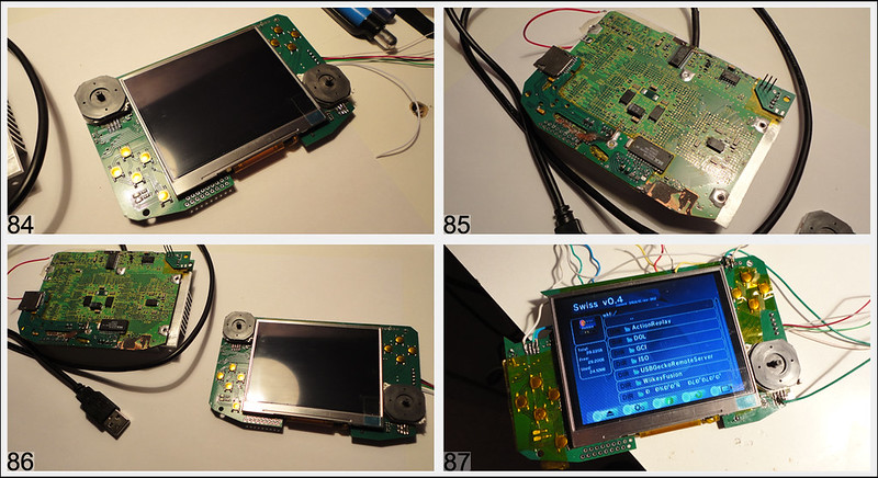
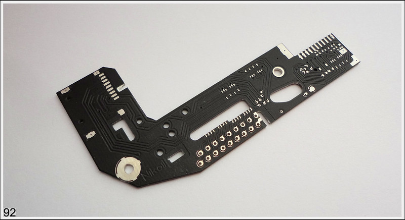
26576413236_3e81c5bd50_c.jpg


Tft lcd, gamepad, wasp, sd\memcard board working fine. But I'm not happy:( And i forgot put in this pcb amp )

33091450334_396452f931_c.jpg


3ds triggers without mounting. Only 4 wires. Its no good. I have new cool idea. Will be in new pcb ver.

33777352732_e739315c3c_c.jpg


v2 memory card/sd gecko/wasp wires pcb

33893854936_2e88e560ee_c.jpg


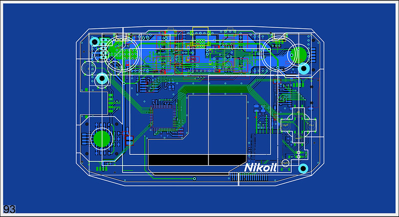
The portable gamecube assembly on pic.93 . All bugs fixed. Added front buttons panel and back speaker panel - this drawing need for quality cutting. I will be make it on cnc.

33777595942_131f64e5eb_c.jpg


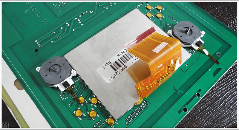
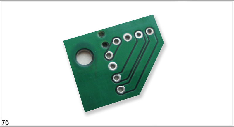
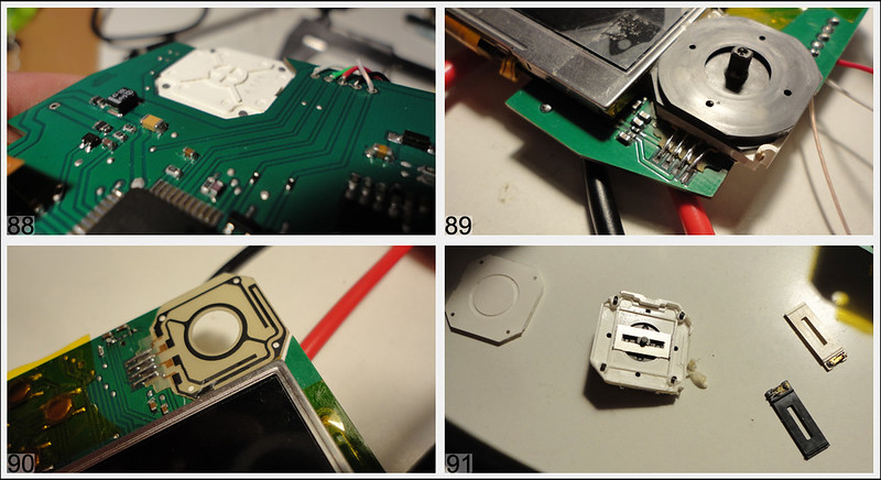
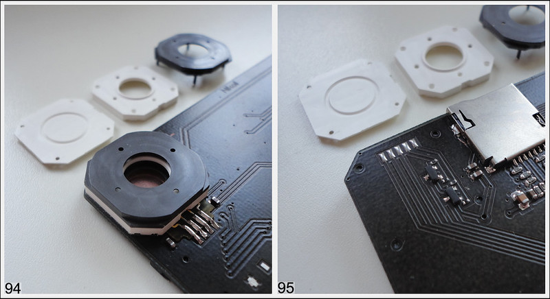
Disassembled analogue stick. Total was 3 pcs plastic parts. I use only 2. Only one click and part installed! Without glue, screw or another dubious ways. This much better then was see 88-91pic

33894158896_589f18c5b0_c.jpg


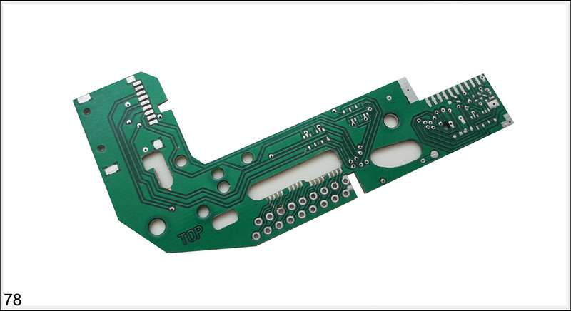
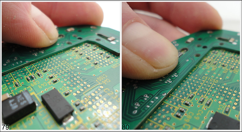
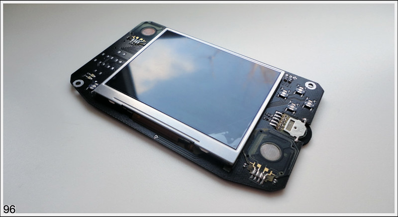
Main pcb - assembly process. Need select buttons for the cross button. Its will be when i get my front button panel.

33122208403_e3ed02fb11_c.jpg


And main pcb - FINISHED
 
Last edited:
Holly flax! That is really amazing work... It all looks so professionnal. I've never seen anyone do such adavanced things for a gamecube portable.
And can I get a link for that screen please? :p
 
This is amazing. Such planning and detail shows serious dedication, which I respect. It's also very cool to see something so different and new done with a GameCube portable.
 
Truly incredible. Why haven't you just removed the CPU and GPU from the gamecube motherboard and BGA soldered them to your custom circuit board at this point? You have done essentially everything else.
 
Back
Top