Naimlessones 2nd Unnamed N64p

naimlessone

Active Member
So, I've decided while I'm waiting for more drive replacements to become available for my GCp, why not make another N64p and put to use some of the parts I have laying around my little work area that are just waiting to become something fun.

I have literally just started to look at different parts and pieces to decide how I want to make it and with what parts, so here is a short list of what I've come up with so far:

~3.5" TFT amazon.com back-up monitor
~A & B buttons from an old GBA
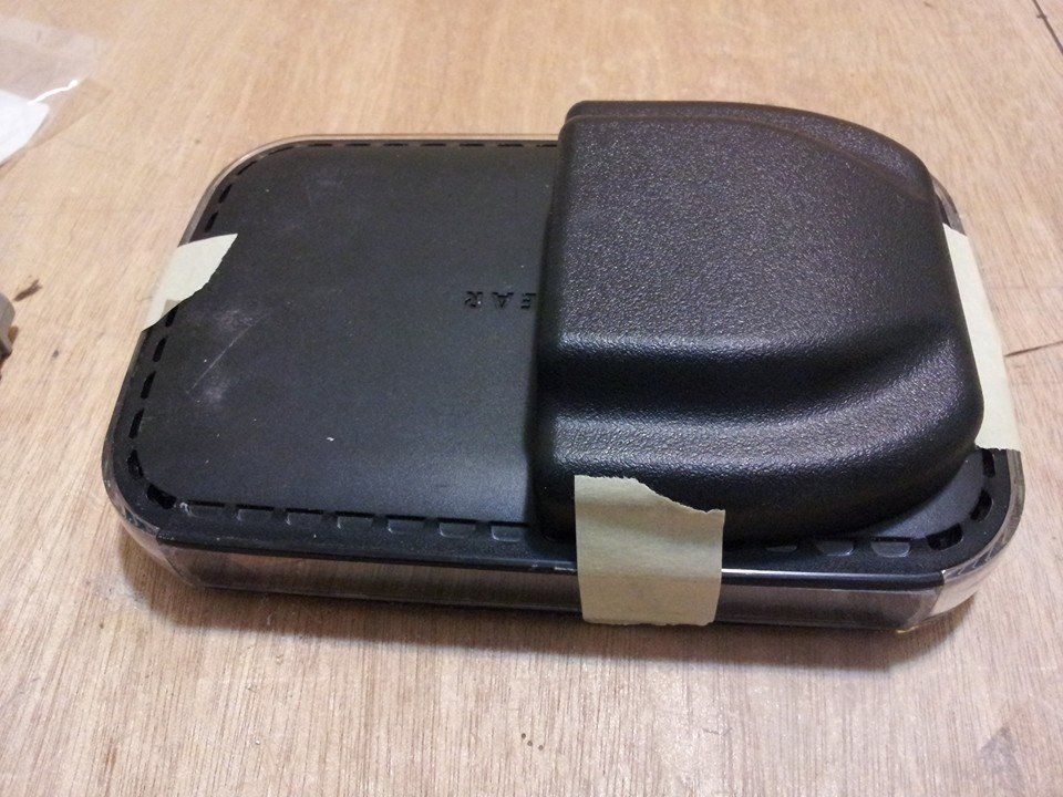
~Inspired by Miceenos Nintendo Sixty 4or the Win, I'm gonna try and make this thing really small and use a Netgear Router case as the housing
~3ds analog slider
~3rd party YOBO controller and C-buttons
~PSP speakers
~Switching headphone jack
~Custom PAM 8403 audio amp and wheel pot
~Ashens 90 degree alternative to RCP wiring
~Salvaged rev6 board (if I can fix the broken traces from a dremel slip)
~Left-over 2200mAh batteries from my first N64p


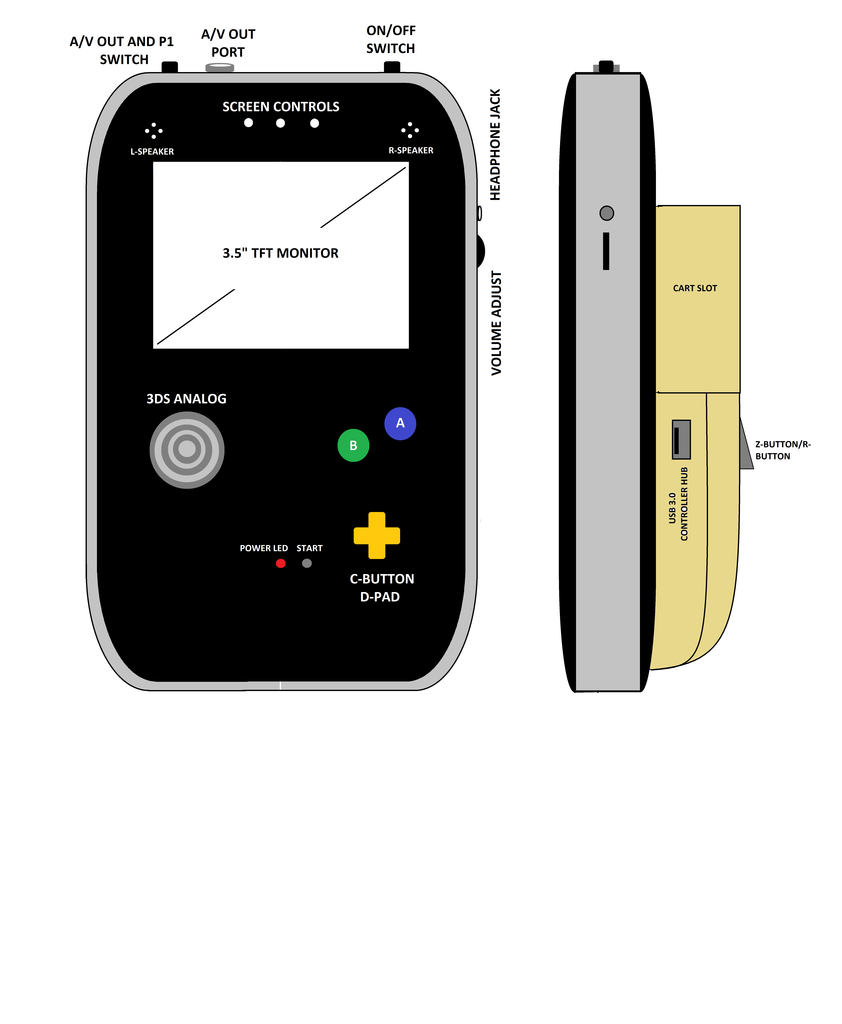
I still have some things I need to figure out with the layout and the orientation of the portable; right now I think I want to try to make it a more vertical 'Gameboy-ish' style portable.

I also want to try to make a controller hub to allow for multiplayer as well, but we'll see how much room I will have because every square mm is going to count on this one.

Also, while this will be going on at the same time as my GCp build, there may be some quiet time while I continue working on that project.

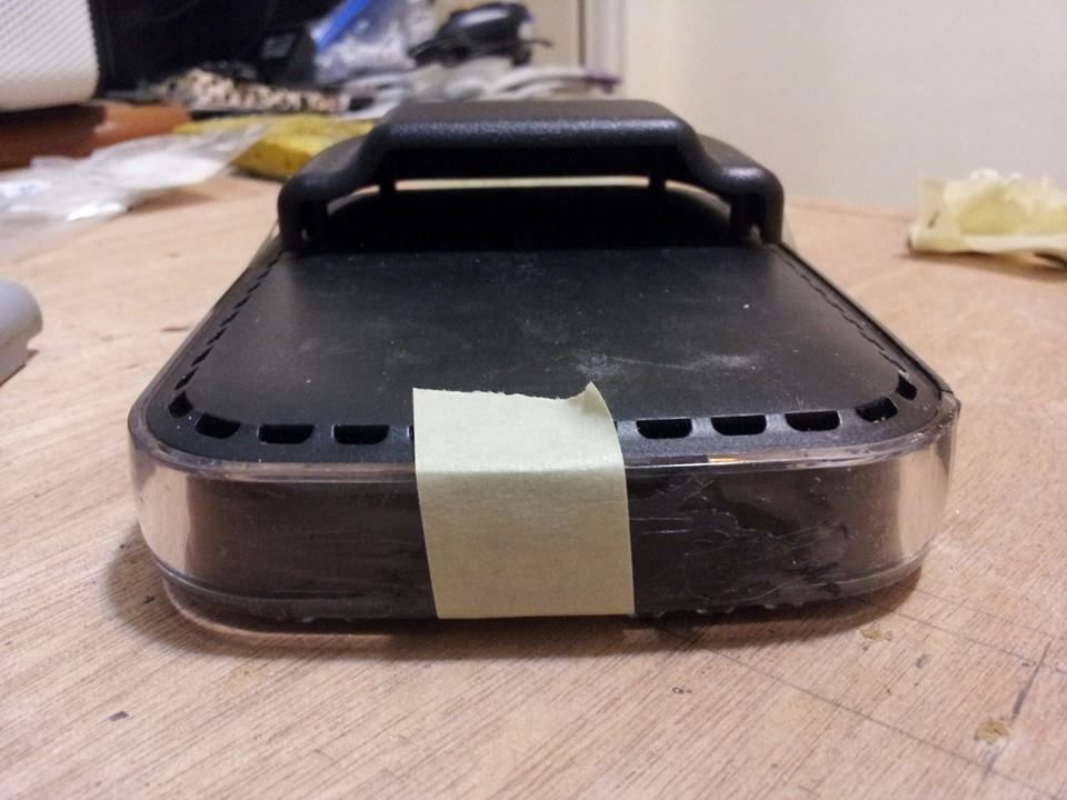
pic of the case i'll try to utilize and the vertical orientation:
2%20Netgear%20Router2012081001032458.jpg
 
Good luck Naimlessones! Try to do it without a spacer. I couldn't trim my controller board small enough to fit in the space I made for it so I had to increase the thickness.
 
Thanks Miceeno. I would love to see if I can. Obviously I would want this to be comfortable for anyone to use, but because I'm going to probably going to keep this one, I want to make it comfortable for my hands, which are kind of big, but lanky as well lol. My initial thoughts about the design were to incorporate the smallest AG-series case that polycase.com has, the AG-43, which is about the perfect width to go across the back of this case..


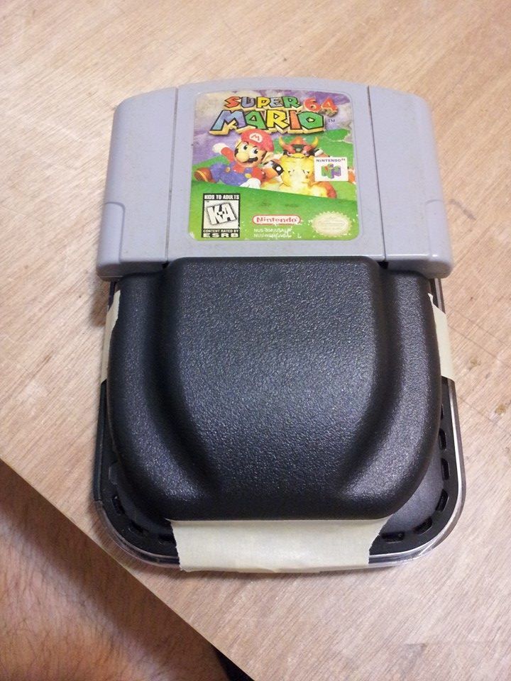
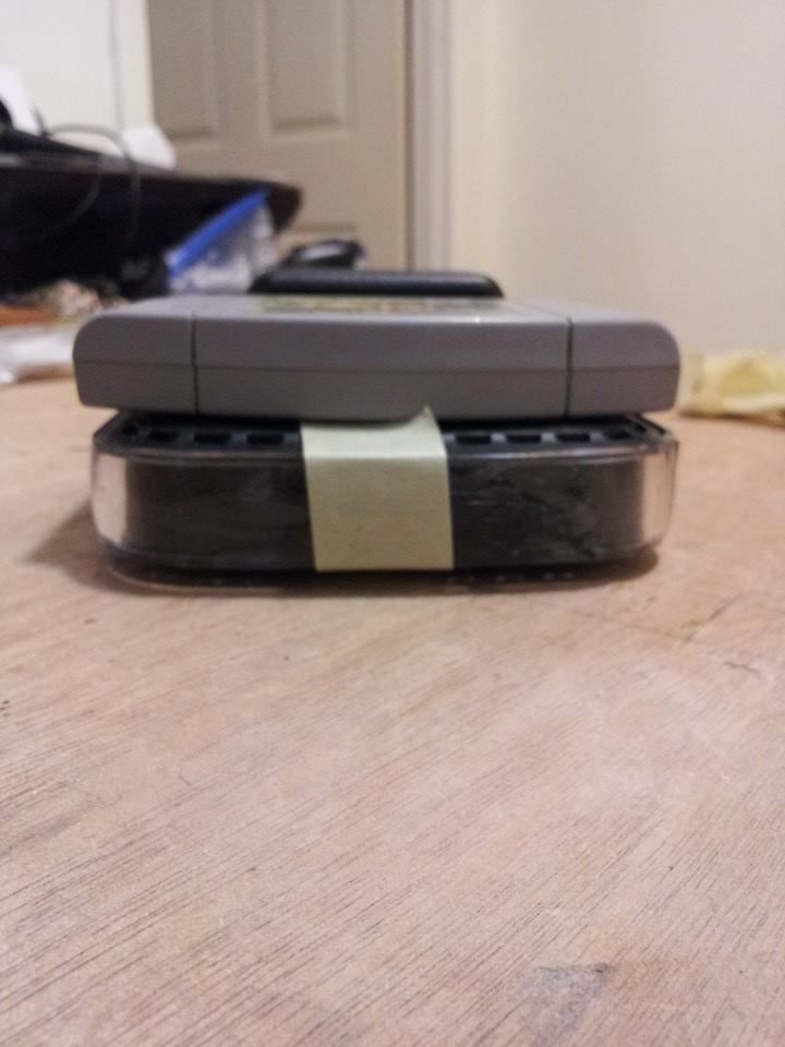
Being that I'm going for a vertical orientation with this one (my previous n64 was a wider horizontal one), with the cart slot on the outside of the case, I personally feel like it would be goofy looking to have just the cart slot with possibly a spacer to extend the case as it would be pretty top heavy, which is why I will stack the cart slot on top of the AG extension. With that extension I should also have enough room to house the batteries I want to stuff in this lol.

I also plan to have a controller hub for multiplayer, much like my plan for my GCp, via USB 3.0 cable.

Here's a pic of the design i'm going for (not this color scheme though lol):


I don't want to put the d-pad in as like the L button, I rarely used. I also am going to try to use the a,b, d-pad and start buttons from a gba shell along wit hthe pcb parts to go as thin as I can while still having the squishyness to the buttons.
 
If you are dropping the L button and the D-pad you might as well drop the A/V out and the Controller Expansion. Why do this? (1) multiplayer on a 3 inch screen is pretty bad (2) you might as well use a stock N64 if you plan to use A/V out and multiplayer and (3) even if you plan single player with A/V most modern TV's don't take kindly to composite any way. What I'm basically getting at is there's almost no space saving to be had by dropping the L button and the D-pad. And the L button and the D-pad are going to be used more often than the A/V out and the Controller Expansion.

Other than my gripe about dropping buttons while adding semi-useful features I'd say I like the design. I have considered making one game boy style like this as well. I recently picked up another router case from a thrift store to do so. The thing I want to do differently is make the 4 batteries removable like the original game boy (for nostalgia sake). I've got a bunch of these li-on batteries around to use, and they even sell a battery holder for them (to make them removable like regular batteries).
 
Yeah, I can't say I disagree with you. And, after thinking about it, I think I will omit the a/v out port and switch along with the controller hub on this one. Depending on how much clearance I have I may even use the c-buttons from the 3rd party controller and move the d-pad to the left side.

I found some tact switches that came with switch caps as well after cleaning my work area this weekend as well. They will work perfectly on a small pcb board and fits very well in the back ag case.

I received my ag-43 cases from poly case this weekend as well! Now I just need to tear down the N64 and start cleaning that up and trimming it down to fit it inside the case. Hopefully I can get a bunch done this week because I've been waiting for this stuff to come in to do anything major so far.
 
Update!

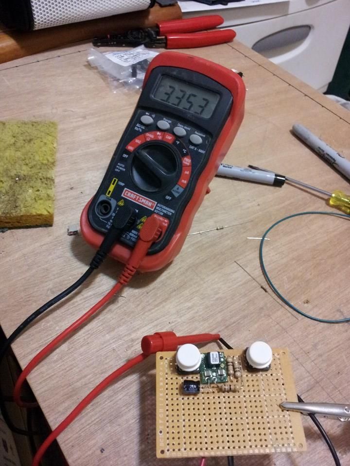
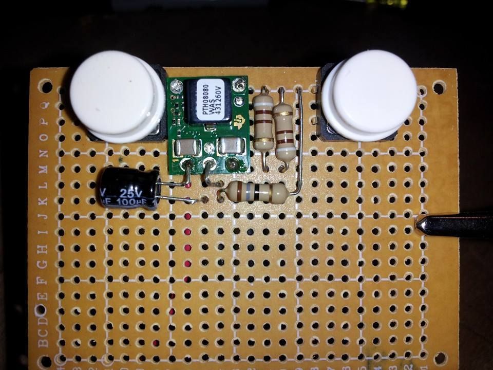
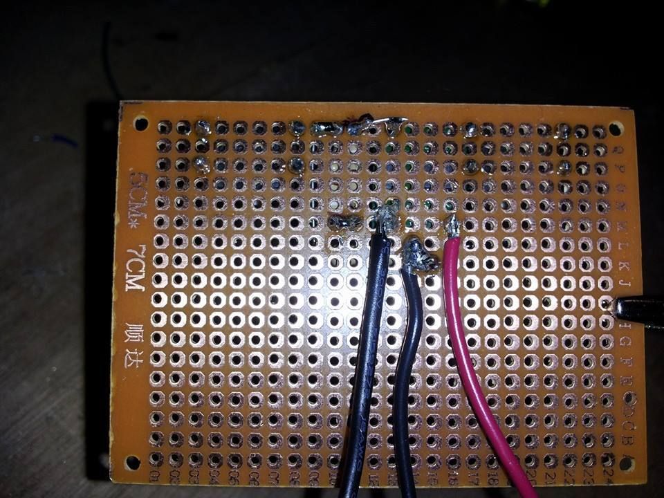
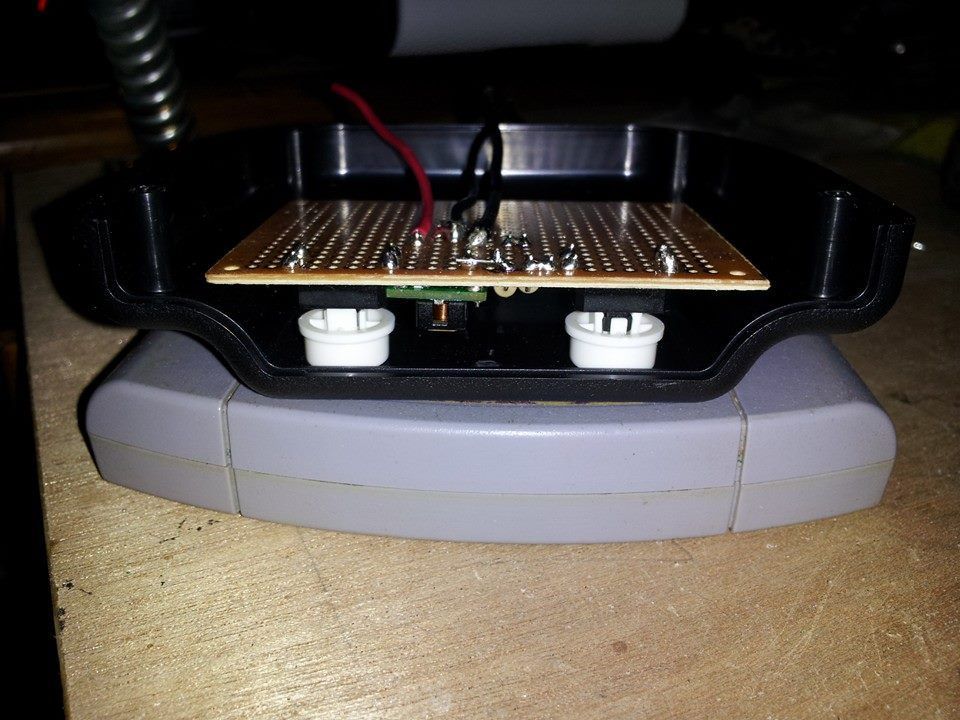
So I did a little work tonight on the voltage regulator and found a pretty good space to mount it where it would otherwise have been wasted.


I haven't cut the holes in for the two buttons yet so they are still sticking up a little bit. It will sit in much closer when I do though.

Also joined the clear ring that goes around the case with a piece of lexan, just waiting for the epoxy to dry.


still would need to make a slot for the cartridge to set inside, but that will be after I tear apart the vict.... console.

Also, I believe I have seen where someone has hard wired the expansion pack to the contacts on the port... I know bentomo has a sticky for reverse engineering the jumper pack so that it's right there on the board, and there is also the fact the exp pack can be bent, but is it possible to solder the traces from the exp pack to the port contacts? Or is that the RAM swap method?

Kinda confused on that. Just trying to come up with something I can do to save from having to put a spacer in there... any suggestions??
 
I really like how the cart fits flush with the shell. Do you really need to have something covering it? Im not too familiar with nintendo 64, but if its structurally sound I say leave it exposed
 
I dont know if I will cover the while cart, minus the very top, or just make some small sides along the edge of cart to leave the picture on the cartridge exposed yet. Depends on how the cart slot port fits ib there.
 
Also, I believe I have seen where someone has hard wired the expansion pack to the contacts on the port... I know bentomo has a sticky for reverse engineering the jumper pack so that it's right there on the board, and there is also the fact the exp pack can be bent, but is it possible to solder the traces from the exp pack to the port contacts? Or is that the RAM swap method?

You have 3 options:


1. Reverse engineering+ram swap:

You do the jumper pak reverse engineering by bentomo+ you remove the two 2mb ram chip from the n64 and replace them from 2 other 4mb chip taken from a rev6+ n64 or an expansion pak.
This works because when the n64 boots, it doesn't check if it has an expansion pak in, it just check the total ram it has, so 8mb here. The jumper pak just "jump the circuit" so the n64 works.

2. Bending the expansion pak:

Save some place, pretty sure it would fit in your case, just not the best with cooling ('cause the expansion pak's ram chip is aligned with the n64 one, except if you take a rev with just one chip).

3. Soldering expansion pak directly to the board.

You remove the expansion pak slot from the n64 (best way is with a heat gun for me) the same way you do for jumper pak reverse engineering, then you solder each of the 36 copper pad from the expansion pak(the ones that make contact to the port when you insert it) to the n64 motherboard with wires(awg 30 is best, MAX 2cm lenght, best is 1.5 cm)


The easiest one is bending off course. I prefer ram swap instead of soldering expansion pak to the board, job is cleaner, more easy to cool... but both require strong soldering skills! Up to you! Would start with bending and if you don't like it, never too late to remove the chip from it and do a ram swap!
 
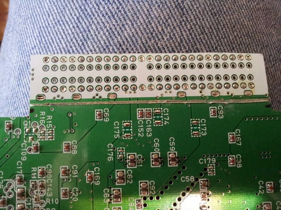
I know this a really noob-ish question, but what are those yellow, plastic sheets with holes you used to attach the motherboard to? I know I've seen them before, but I forgot what they're called..
 
RetroNuva10 said:
I know this a really noob-ish question, but what are those yellow, plastic sheets with holes you used to attach the motherboard to? I know I've seen them before, but I forgot what they're called..

Its a breadboard, you can use it to surface mount components as shown in the image.
 
BTW, does anyone know of a good guide for the RAM swap method?

Or can someone explain the process for me?

I'm definitely going to need to do this in order to make this fit in this case without the need of a spacer lol.

I'm wondering if this information is correct?
FierceDeity said:
Actually, the Expansion pack contains 4mb of ram. N64 boards revisions 1-5 all have 2, 2mb ram chips. Revisions 6-9 have 1, 4mb ram chip. To ramswap, you have to get a revision 1,2,3,4, or 5 board, take off the 2 ramchips, and replace them with ramchips from a expansion pack or a revision 6,7,8 or 9 board.

As for how to take off/put on new ramchips, this video teaches you what you need to know about Surface Mount Soldering-
http://www.youtube.com/watch?v=3NN7UGWYmBY

And if so, I'm using a rev 4 board, I would remove the two ram chips below the cpu and can replace one with an expansion pack chip and I can take one from say a rev 6 board?
 
There was an awesome one on shockslayer forums, but the site seems to be down...

The technic for removing the 2mb chips is to cut the two littles pads holding the ram:

0ab74de4d20e7fa9af218a52963246c4.jpg


then lift it up and tilt it foward/backward until it gets off, than pass slowly on each pin of the board with your soldering iron to remove the pins of the chip.


For desoldering your 4mb ram chips, there are many ways, the easiest one in my opinion is to use a heat gun, but it's also dangerous that you burn the chips if you can't gauge the heating right. The other one, the one that I prefer but that is longer, is to use desoldering braid:

Desoldering-braid.jpg


Apply flux on the pins of the chip than put desoldering braid on it and heat it than move slowly from one pin to another, many times. Than lift it up, be REALLY careful that pins don't break from the chip. There are many desoldering guides out there.


And yeah, the information you found is right, and yeah you can take chips from rev-6 and expandosion pack, the 2mb chips are labeled NUS18 and 4mb chips are labeled NUS36.

Be careful if you find "unofficial" expansion pack that are not made by nintendo, some have 2 2mb chips, but if you're lucky you can find 4mb chip in it.
 
Okay Supersonic. I ordered some chip quik off amazon just to make my life easier to swap that out as I also don't have a heat gun.


Also to be for sure, when I do the ram swap, all the system needs to have in the expansion slot is a jumper pack?


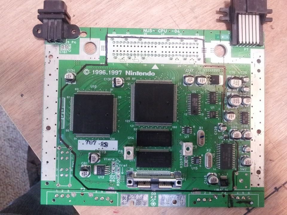
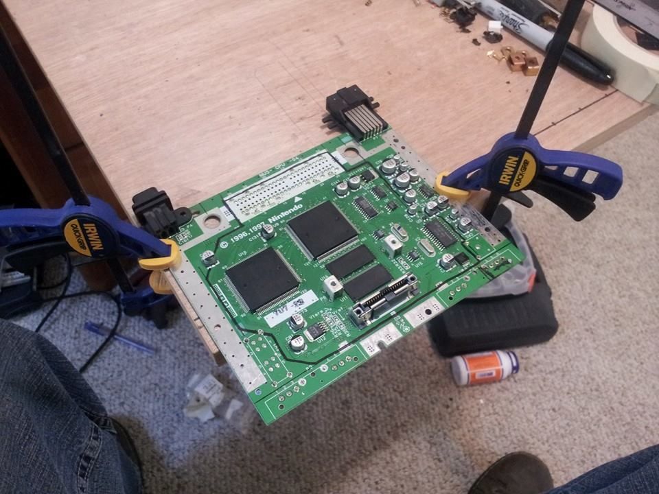
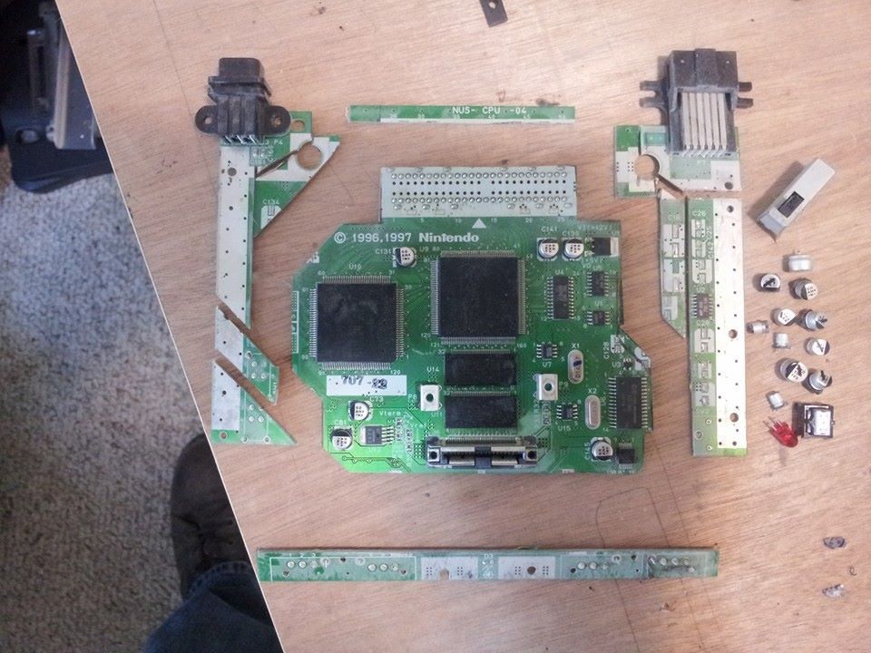
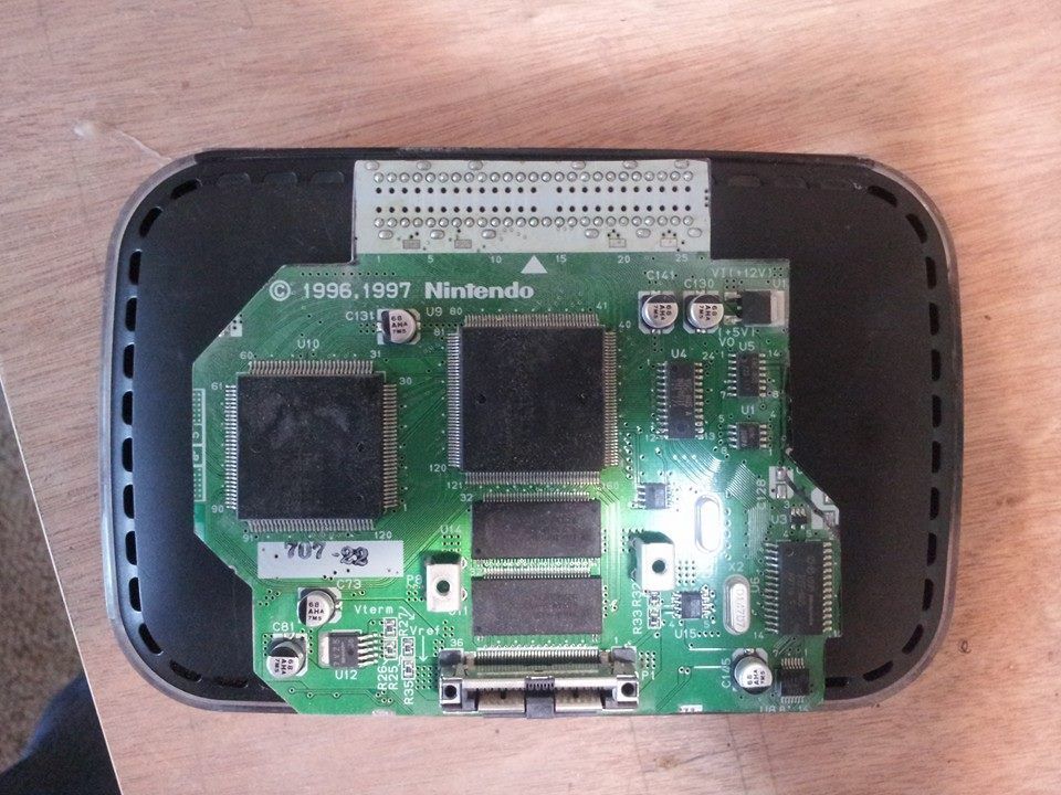
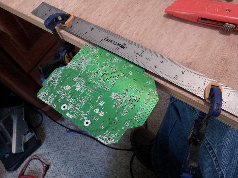
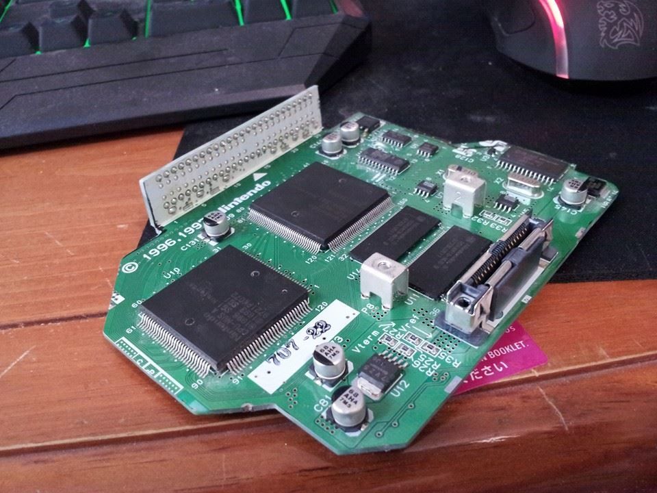
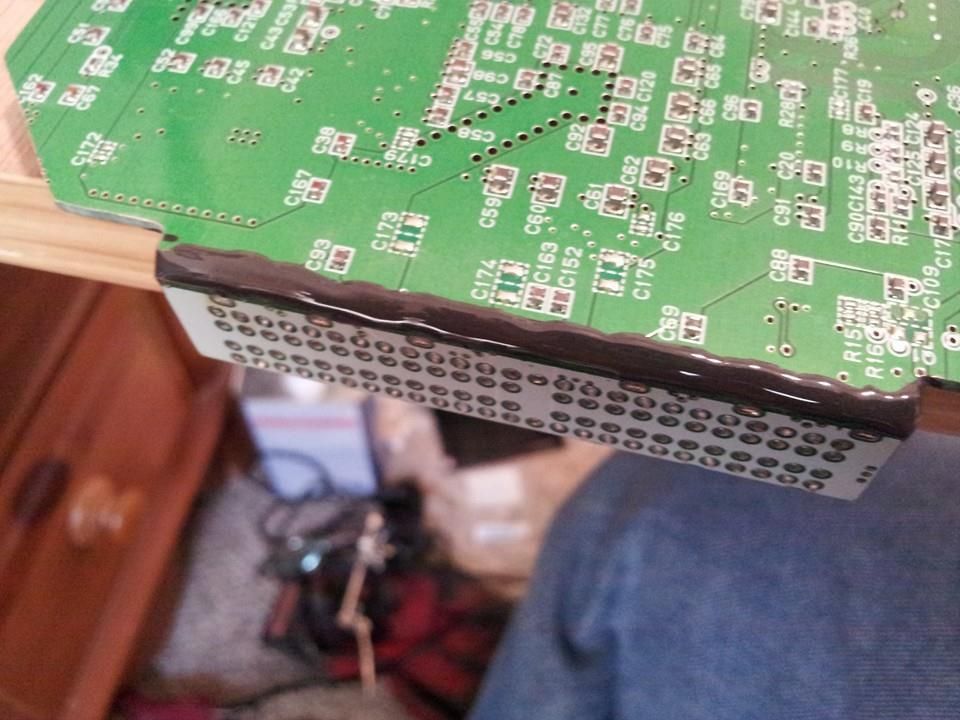
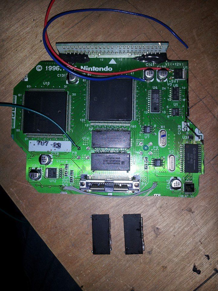
A little more progress: I went ahead and trimmed up rev 4 board according to bud's N64 trimming guide and am very pleased with how it came out:


Then did Ashen's Alternative to RCP wiring 90degree bend:


and epoxied it in place (i'll reconnect 3.3v lines when I wire the cart slot back in):


Now all that is left is to finish!

I can probably get started on the case work, but as I am playing in a dart tourney tomorrow through the weekend, I'm gonna relax a little bit and wait for the chip quik to come in the mail.
 
Exactly, just so you understand, imagine that your n64 is splited in two, you have a right side and a left side, the jumper pak is like a trace that connect these two parts so the circuit is complete. When you have an expansion pak in, it's the same thing but the n64 detect 4mb extra ram, so with ram swap and a jumper pak you get the same thing.
 
Little update!

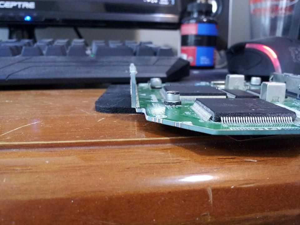
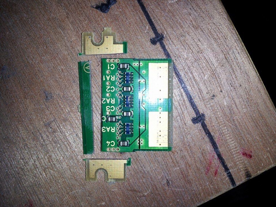
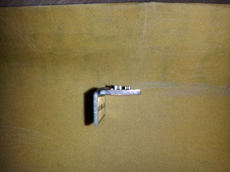
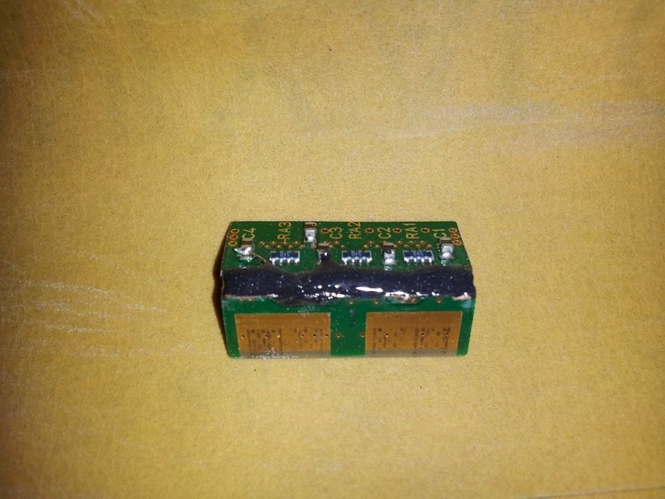
Trimmed up the jumper pack and bent it 90 degrees:


Also performed the ram swap with the chipquik kit I got in the mail Monday:


Still need to trace out the controller mobo to try and minimize the size of it as much as I can. I can already see just how difficult it was for Micceno to do this without a spacer; flax is gonna be tight lol.

Still mocking up where everything will layout.

Also ordered a broken Nintendo DS on ebay to scavenge for buttons for the N64 c-buttons instead of using a d-pad for them. Should actually save a lot of room as well as I will be using the pcb for the buttons from the DS mobo. Only problem I can see right now is having clearance for the screen to fit above the bent jumper pack.


I had also posted a question in the General Modding and Electronics section about using a regular wall wort to power this thing off of wall power, so say if you were laying in bed and wanted to play without using a battery you could.

I know the power pack that you use with the regular n64 console outputs your 3.3 and 12v needed to power this at 2.7A and .8A respectively.

Does anyone know if you could use a power pack like this:
http://www.allelectronics.com/make-a-st ... ply/1.html

along with the 3.3v regulator internal to the portable?

Obviously I'd have to put a switch in to go between battery and wall power, I just don't know if a power pack like that would power it for sure without problems or not.

Should get some more work done on this this weekend. I wanna start doing some case work pretty soon after I get everything tested out and verified working.
 
So I have run into a problem...

I have rewired the cart slot making sure to double check my connections, hooked up the screen, audio amp and voltage reg and reconnected the 3.3v traces on the back and to the 90 degree fold for the cart slot and am getting nothing on the screen.

The screen does work, menu buttons and all and I am getting some sound on the amp, though not game sound from either Mario 64 or Zelda: OoT.

I thought that after the RAM swap that some of the traces weren't making good connectivity so I went back over them with the iron and some solder. Nothing looks to be bridged.

I grabbed a different jumper pack than the one I trimmed and bent to eliminate the possibility of that being a problem.

I tried the 2k resistor fix between pin 8 on the PIF and 3.3v. Nothing.

I even thought that maybe the voltage on the 3.3v reg was a little high at 3.355v so i put a different resistor in and brought it down to 3.26v and no change.


Anyone have any thoughts on what to try next?
 
Back
Top