Why doesn't a pull-up resistor short a circuit?

legofan623

Well-Known Member
I have been looking at a lot of examples of circuits that require a pull-up or pull-down resistor for input pins to keep them high or low, rather than floating. Take a look at this diagram:

511568b6ce395f1b40000000.jpg


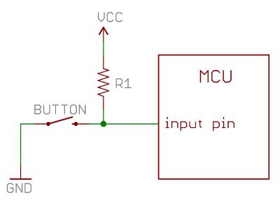
What I want to know is why, when the button is pressed, having GND and R1 connect doesn't fry the circuit, and rather it seems to override the resistor's (high) voltage to the input pin, and the input pin becomes (low) GND. It's like the resistor just vanishes from the circuit when the button gets pressed, and reappears when it's not pressed. Isn't there still a considerable amount of voltage coming out of the resistor?
 
Voltage is defined as a potential difference; it is always measured by comparing two nodes. When someone refers to the voltage of a single node, it is assumed that the node it is being compared to is Ground, which is defined as being 0 volts (because the potential of ground minus the potential of ground is zero). As for what a node is, there is a node between every component (I will not consider the switch to be a component as it is merely a connection or not). So for this circuit we have essentially three nodes, VCC, GND, and, oh, let's call the other node V1, which will exist between the resistor, the chip, and the switch.

When the switch is in the open state, you have VCC connected to V1 by a resistor. The voltage at V1 is not equal to VCC, but rather VCC - Vr, such that Vr is the voltage on the resistor (since the MCU is a blackbox, I can't calculate what that will be, but it likely won't be very high).

When the switch is in the closed state, there is a short circuit between V1 and GND, meaning V1 IS GND, thus the MCU has an input of zero volts.

Another way to look at it is that electricity follows the path of least resistance. The MCU has a non-zero resistance associated with its input pin, while the path through the switch directly to ground has zero resistance. Whenever you're dealing with zero resistance versus non-zero resistance, it always goes completely down the path of no resistance. If there was a resistor between the switch and ground (or between the switch and V1) then it would no longer be a short circuit to ground and then there would be some voltage at V1.
 
Don't forget to mention Ohm's Law. In my opinion the easiest way to explain shorts.

V = I x R

voltage = current x resistance

Which can also be expressed as V/R = I.

When you attach 5v to 0v (GND) with a wire or some other conductor this creates a very small resistance, say .01 Ohms for example.

Now going back to the equation you suddenly have 5v/.01ohms = 500 AMPS!!! Or whatever the maximum amperage that can be supplied by the 5v source. Which typically will still be enough to hurt many integrated circuits.

A pull up resistor increases this resistance, so when you connect 0v (gnd) to the input pin to pull it down there is only a few mA or microA on the resistor.

Another thing to note, input pins of any logic device has an extremely high input resistance, in the tens of megaohms. So there is no current being drawn on the pin, or at least it's very tiny, and when no current is drawn on a resistor the voltage will be the same on each side. So it can be pulled up to 5v when in normal operation, and when it's pulled down to zero with the switch the resistor prevents the whole system from shorting.
 
Wow, thanks for the great answers! So it DOES short, but the current through the resistor is so miniscule that it causes no real damage? That's really interesting... With that I guess my next question is that wouldn't a diode make more sense for this application?
 
legofan623 said:
Wow, thanks for the great answers! So it DOES short, but the current through the resistor is so miniscule that it causes no real damage? That's really interesting... With that I guess my next question is that wouldn't a diode make more sense for this application?
A short circuit is not always a bad thing, it's when your voltage source is shorted to ground that you have an issue. In this case it's not VCC getting shorted to ground, it's the MCU's input pin getting shorted to ground, which is no problem. There is a current that goes to ground, but it is equal to VCC/R because there is a resistor between the voltage source and ground. Even something as low as, say, 220 ohms on a 5V node would result in a current of only 23 mA.

As for a diode, I don't understand what you hope to accomplish by using it here.

edit:
I think I see what you're trying to do, but no, it would not at all be a good idea. Assuming you have the diode biased so that current can flow from VCC, here are the two circuits you'll have: (note, I'm not going to go into full detail of how diodes work and just stick with a simplification for conceptual purposes)

Switch is open: voltage VCC goes to MCU input pin. Everything is fine.

Switch is closed: Voltage VCC is directly shorted to ground, current jumps up to a billion amps and the world explodes. Everyone is dead and it's all your fault for using a diode instead of a resistor.

so in summation, using a diode here is pretty much the same as just skipping the diode and shorting VCC directly to the the switch/MCU pin and that would be bad.
 
grossaffe said:
Voltage VCC is directly shorted to ground, current jumps up to a billion amps and the world explodes. Everyone is dead and it's all your fault for using a diode instead of a resistor.

grossaffe is right, Diodes do not limit current in the forward direction, only prevent it from flowing backwards, (To an extent).
 
Crap I guess I made it to late. But another thing about diodes they have a voltage drop across them, they don't just protect against back current.
 
Back
Top