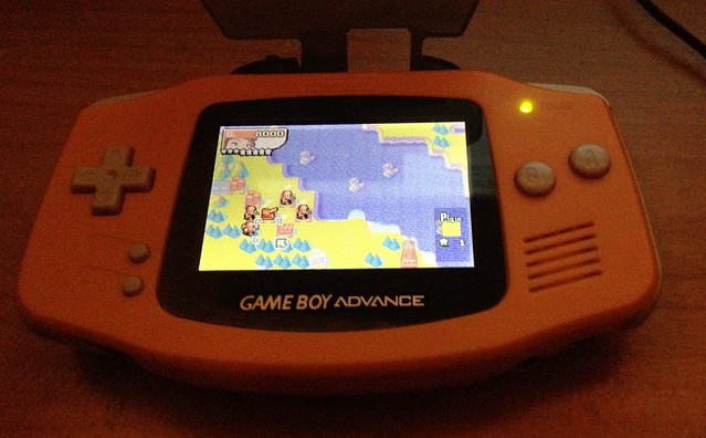
classic GBA with GBASP lcd mod!!!!

http://www.ebay.com/itm/Nintendo-GBA-SP ... 2c5f52b341

any chance this is the right one? don't see much for replacement sp screens, and its a bit more costly then I thought it would be at $30++ since ds and psp replacement screens are $10-$15
I'm starting to wonder is any of the ds series of screens would work? i know the cable don't line up the same, but if it was to get wired in place anyway. perhaps?
 
guys, i`ve been hotmailing the guy who made the item, and he says he will ebay it soon. he didn`t say when, but at least we know it will be at a more familiar page :p

(btw, i didn`t imagine this would become a hot topic hehe :p )
 
I'll give y'all a month to figure it out, befor I buy one to do so. the down side will be having to buy five of the more costly sp 101. I'm hoping fo find some replacement screens for it at a better price.
 
guys, i`ve been reading some of the tutorials this guy has sent to me, and as far as i could understand, he makes 2 types of ribbon. one for the 32-pin model and another for the 40-pin model. both models need a different ribbon cable, but both of them make the lcd work. it only uses one soldiering point, so the chances of screwing it up is only about 5%.

some of the pros or someone who can actually buy from taobao should try this soon and tell us the results
 
On the 32 pin one , he is using a 34 pin ffc extension. Then he just cuts off the last two pins. Then you wire the 2nd to the last pin to 3v source for the backlight.

The extension is so you can flip the lcd and fit it in the GBA in the proper orientation.

It's basically about a $10 mod with parts from digikey.
 
Would you mind detailing with links from digikey what parts were used. This would be a great and easy mod for people who love the original gba.
 
I'm on it.

It's the last on the 34 pin ffc that provides power to the backlight. Around 10.5v
You have to connect it to the cap on the Original GBA to power the backlight. That cap puts out around 12.5v.
That is why the backlight is slightly brighter when used on the Original GBA.

I can get 34 pin zif connectors, but you will need 2 of them and then solder them back to back. Or you can buy one and wedge the two ffc's together in it. But that will leave you with a bigger connector to try to shove back in the Gba when re-assembling. And the ffc is flipped over , that is why you can't just plug it into the GBA board, it needs to be totally flipped pin-wise.

I'm thinking the two zifs soldered back to back is the way to go, but I am still checking on it.

*edit* In fact looking at it I'm 99% sure he has two zif connectors soldered back to back. I think he used sm zif's and then just soldered them back to back like you would solder a sm part onto a board. I am going to buy some connectors and see.
 
whats the chances of desoldering the conector from the GBA SP and it still be usable?
Im thinking of pulling the connectors from the GBA and GBA SP, and do the flip almost directly to the board. I need to get some low heat solder.

my thought was, doing this mod you will no longer have a need for the SP mobo.
and already have the connector that would be useless otherwise.

Might as well wire up the SP battery to the GBA wile your at it.
 
I finally got my cable and screen from that seller on taobao. I don't think the screen itself is an official GBA SP backlit screen, but rather a cheap reproduction. Why? It has a terribly low refresh rate (ghosting) and I can practically see the lines scanning. But, I've never seen an ags-101 before, so I have no reference anyway. Regardless, I may try to source an ags-101 anyway, and try that out.

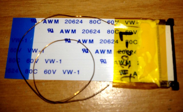
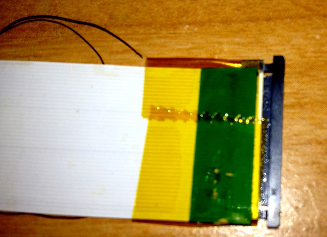
Anyway, as far I can tell, the (40-pin) cable is just merely an extension for the LCD with an added wire to power the backlight. The reason for this, for those that don't know, is that the standard gba screen, the cable is on the top, and for the GBA SP screen the cable originates out of the bottom of the screen.

(I tried to get as clear of a picture as possible, but my only camera is my iphone)
7619311388_a8d7fdc016_z.jpg

7619311942_7d6e01a54a_z.jpg


Installation was fairly straightforward after following the pdf install guide. I translated it via google translate, but to be honest, the pictures did a pretty good job anyway. This mod will require you to shave away some plastic from the inside of the front faceplate. I just used a dremel, but I'm sure a hobby knife would work just fine.

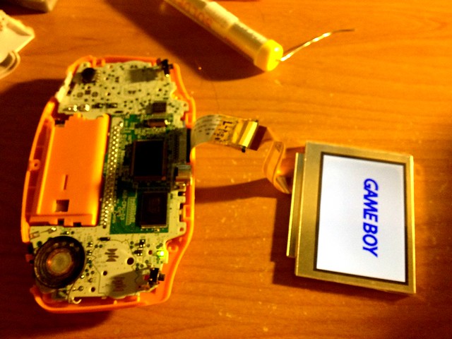
Me testing the screen:
7619312390_2aff544a6f_z.jpg


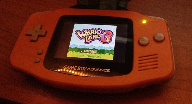
And all put together:
7619313102_97bb3a584e_z.jpg

7619313572_c6be4822a3_z.jpg


I'm satisfied with how it looks and works, but as I said, perhaps I'll cannibalize an ags-101 in the future.
 
ssssso, does any of you guys figure a way to make that extention? cause i couldn`t buy it online for multiple reasons :S
 
superben51 said:
To hand solder a extension for the FFC would be incredibly hard to do with out vaporizing it.

but it seems in the picture like it`s just taped all over. and i really want that mod :(
 
To hand solder a FFC like the white one is not all that hard, you just have to move fast but one like coming right out of the screen (the orange one) would be insane.
 
Back
Top