Another GBA:SP in a DMG Case - Need some help with tacts

Hello! Long time lurker, first time poster here.

I've been working on and off this project for a few weeks now, and, basically, I'm putting my GBA:SP inside an Original Gameboy casing. I know you've all seen it before, but I'd really like to do it too.

I've gone through 3 SP's so far. (First one I ruined trying to desolder the cartridge slot, the second I ruined trying to relocate the power switch, and the third I ruined by accidentally shorting the motherboard while not properly securing the battery when testing out buttons.

So here are a few pictures of where I'm at. (I know, I didn't do the best dremel-job, but it will suffice for a first modding project.)


Front cover with SP screen inside. Bad dremel job, but hey, it works. (Oh, and I don't know why but this picture makes it look like my DMG is.. curved? Well, it's not.)


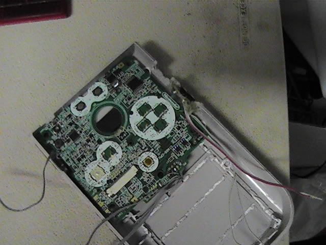
Back cover. The black buttons are the L and R buttons, and the big tangle of wires is soldered to an extra cartridge slot for relocation.


Battery cover. The rechargeable battery is superglued to the cover along with an extra "battery connection port". I will end up soldering the wires to where the battery connection port-thingy is on the motherboard.


Salvaged headphone jack from the DMG. Not sure exactly how to connect it to the SP motherboard, any advice? I'd like to use the original speaker and headphone jack, and make it so that whenever I plug in the headphones, the sound turns off from the speakers.


Cut-off part of the DMG motherboard, what I will be connecting to the tact switches with. This is my main question:

How do I connect the tact switches on the SP motherboard to the tact switches on the DMG motherboard? I tried soldering, but I realized that the DMG motherboard doesn't have anything to actually solder to, based on the picture of what I'm using, anyway. Any help?

Thanks everyone.
 
Update.

So, with my limited knowledge of wiring, I just realized that I could simply scratch off part of the board to show the copper and solder to that. Makes my life easier!

So now my question will be refined to:

Should I wire to the contacts on the SP board underneath the tact switch, or on the sides of the tact switch (where the switch is connected to the board)?

I'll post pics of what I mean in a few minutes.

EDIT: Here are some pics.


(Sorry for the small font) This picture shows the exposed copper that I'm going to solder to on the DMG motherboard. Should I simply solder one side of the tact switch to one of the two parts of the exposed copper, and the other side to the other part? If that makes any sense...


(Sorry again for the small font) This one shows what's beneath the tact switches on the SP motherboard. Should I wire from the corners to the DMG motherboard, or from the spots on the switch?

Thanks again.
 
You just *Can'tSayThisOnTV*ed up that board. Don't scrape the carbon right off of the button pad. Follow the trace to a location not directly under the button and scrape away the insulation somewhere else.
 
Sorry for linking the post! I just copied and pasted directly from my post on another forum.

Palmer directed me to ModRetro, and from what I've seen so far, I like it!

As for the scratching off... er... too late. :/

Will the DMG tacts still work if I just don't solder it where I scratched off, and trace the wire to another location and solder at that point?

EDIT:
Dang! Is this board useless now?

I suppose if it is I can always just use tactile switches bought at a retail store, instead of the DMG ones, though I would have really liked to use those ones for simplicity's sake.
 
Follow the trace from the pad and solder to the trace. Then use a common ground for all the tacts.
 
Alright, I think I know what to do now.

For the DMG motherboard that I scratched the paint off of: can I just use some nail-polish and add a coat of paint back on the buttons that I scratched off?
 
Aereolaite said:
Sorry for linking the post! I just copied and pasted directly from my post on another forum.

Palmer directed me to ModRetro, and from what I've seen so far, I like it!

As for the scratching off... er... too late. :/

Will the DMG tacts still work if I just don't solder it where I scratched off, and trace the wire to another location and solder at that point?

EDIT:
Dang! Is this board useless now?

I suppose if it is I can always just use tactile switches bought at a retail store, instead of the DMG ones, though I would have really liked to use those ones for simplicity's sake.

Hah, when he said you link'd up the board, he actually said you F^%*'d it up. Our wordfilter changes swear words to some random stuff. :p

Anyhow; just a terminology fix: The DMG buttons are not tact switches, they are membrane switches. Tacts have a solid mechanical "click", these are just traces with a conductive carbon rubber membrane covered by a plastic button. Feels better. :) Your button should actually still work, even though you scraped the carbon (Not really paint) off of it. Worst case, you can just add a very thin layer of solder on top of the bare copper parts.

Here is the tough thing, though: Using the DMG button board is not very simple. Do you have a voltmeter/multimeter/continuity tester? I hope so, because you will need one for this (You can make a continuity tester pretty cheap with an LED and batteries, google it). You see, the DMG does not use a common ground for all the buttons, and they are wired pretty weird, at least in the revisions I have messed a lot with. You CAN get it working, but you will need to strip all the components off of that control board, and cut a few traces, too, then wire it for a common ground.

Oh, another side note: I made mine without relocating the cart slot. ;) Check out this picture:
PIC_0035.jpg


I was able to sand down the plastic on the inside of the cart cover for the DMG to make the SP motherboard fit just like that! Pretty nifty, right? Here is the cart slot:
PIC_0037.jpg


I am sure you have more questions, throw 'em at me. :)

EDIT: Oh yeah, the headphone jack. Let me see if I still have my wiring diagram somewhere.
 
Thanks for the input, Palmer.

I pretty much understand what I've got to do now, as far as wiring the DMG to the SP goes.

I still need a headphone diagram, and thanks for looking for me!

The last real question I have is how to wire the SP power switch to the DMG power switch. Is it possible?
 
Darn, I cannot find it. I would send a PM to the member ShockSlayer and ask him to take a look at this thread, I think he may have done a GBA SP headphone jack mod at one point. You are basically going to have to gut that entire headphone jack board, and only use the actual black headphone jack component, soldering directly to that. One of the pins on it is the headphone switch that will turn off the speaker, all you have to do it wire it to the right place on the GBA SP. The SP actually has all the wiring for headphones, but you cannot use them without a little adapter plug. All you will be doing is soldering straight to the board, bypassing any plugs.

Another piece of input: I think there are cooler ways to handle the screen. Namely, I think you should cut a hole in the plastic of the DMG shell large enough for the GBA SP screen, then mount it INSIDE. Then, you could make a custom screen cover the same size as the original DMG one, but with a larger clear space. All you really need is some thin clear plastic (I know some members here sell perspex for cheap), or even steal it from a CD case. Cut and sand that to size, then mask off one side using tape to make a screen hole large enough. Then, paint the rest of it gray on the backside! It would look pretty awesome. :)

Let me know if you need anything else!


:dah:

That's the video. I have no idea what the pinout is, but this might help.

IMG_0540.jpg


That's a picture of the plug and where I soldered the four wires for the headphone jack, GND, HPS, HPL and HPR.

http://www.hardwarebook.info/Game_Boy_EXT.2

Some documentation on the plug, should help you find everything except HPS, which will be the only one in the picture not yet hooked up.

Enjoy!

SS
 
Thanks ShockSlayer, this will definitely help me.

Update: I've made the screen look a bit better "in place", and I've also spray-painted the case black.

I really need to know, how to hook up the power switch from the DMG to the SP, that should be my last main concern.
 
Sorry for taking so long to reply, I was out of state.

Hooking up the power switch will be... though. :( You might have to just leave it, and have it do nothing. They act in totally different ways, and rigging it to work as a compatible switch will be quite a bit of effort.
 
I can't actually remember how I did the switch in mine...If I can, I'll let you know though! :p
 
Back
Top