bentomo
Frequent Poster
Hello everybody, today I have a little write up for reverse engineering the SD card slot on a wiikey fusion or a wasp fusion.
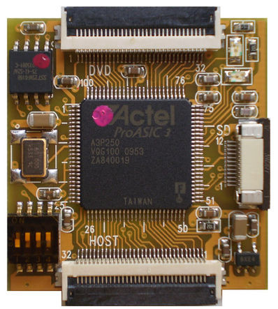
Just a couple things to note is that the wiikey and wasp are true clones. I tore down both a wasp and wiikey sd card slot just to be safe but turns out that they are exactly the same as far as the sd card slots are concerned. I am also using this image for referencing pins: (while confirming with several other sources for naming consistency)

Important note pointed out by megalomaniac
The purpose of this project is purely for portables. The original SD card slot on the wiikey is a little big and the wasp fusion SD card slot is even bigger so it's not exactly ideal for a portable, so the best option is to replace it with a micro SD card slot.
Here are my findings: (pics are a bit big)
Here are the front of the wasp and wiikey fusion SD card slots, obviously nothing interesting here to see.
Wasp WiiKey
Here is the back, even more boring:
Wasp Back Wiikey Back
Here are the boards without any components:
Bare Wasp Bare Wiikey
And here's the wiikey SD card slot after removing the white solder mask:
Wiikey Sanded
So now after some tracing and double checking, both circuits are exactly the same. Even the FFC connector has the same footprint size. Please note that the schematic that I have here has different names for each resistor due to the software that I used to create it, the values of the resistors, however, are clearly labeled on the schematic.

The board consists of 15 components:
Part_________________Package
SD card slot____________Non-Standard
12-pin FFC connector____TBD
10uF capacitor__________SMD 0805
1uf capacitor___________SMD 0603
6x 22.1Ώ resistor________SMD 0603
3x 68.1kΏ resistor_______SMD 0603
470kΏ resistor__________SMD 0603
15kΏ resistor___________SMD 0603
As it turns out the wiikey/wasp does not use the SD card sense lines at all, they're completely disconnected, so any SD card presence sensing for the wiikey/wasp appears to be completely software based.
At the top of the schematic we see two capacitors, a 10uf and a 1uf capacitor between power and gnd, this is just some simple decouple and noise filtering.
Now if you do a little math you can see that most of the voltage is dropping of the 68.1k resistors and going straight to the data line. Your guess is as good as mine for the reason for this but the most probably reason is signal mirror filtering. When high speed signals are sent over long wires (in our case the FFC cable) there tends to be some mirroring forming after long periods of time, so these resistors are there to filter and dampen the ringing. Any comments you guys have would be appreciated. As for the 15k resistor on the clock line this is mostly likely a damping resistor for any ringing that would occur.
So overall the extra components are for filtering and protection. I did discover that if there is no cable plugged into the wiikey it will error out so at least some of the parts or the FFC cable is necessary for proper operation. It could also cause issues on the data lines with long game times so I'd recommend leaving them on.
The cool part
And finally the reason for all this. Here's the front and back of the board that I'm currently having fabricated at OSHpark:

On the right hand side of the board you can see a second adapter for mounting and soldering a micro SD gecko board.
The footprint for the micro sd card slot uses this part from digikey:
http://www.digikey.com/product-detail/en/101-00581-59/101-00581-59-1-ND/2187102
I don't have a part for the FFC connector as I just copied the footprint from the SD card boards. (As I mentioned earlier both FFC connectors share the same footprint)
All the other components are using the standard package sizes from the original board so if you have an original SD card adapter you can transfer the parts over. If you don't or lack any desoldering skills the parts can easily be found on digikey.
----------------------------------------------------------------------------------------------------
UPDATE *07/11/15*
Here's the updated board, it works great except I missed a disconnected ground trace on the connector.
I've updated the pcb files and you can download them here if you're interested here.
http://www.filedropper.com/microsdcard
Or you can just order them straight from the shared PCB way project. It costs $6.60 for 3 with free shipping.
https://oshpark.com/shared_projects/FhOnpaqE
Remember a link to the SD card slot on digikey is hosted above.
Here it is in action, you can see the repaired ground trace with the air wire.


Please leave any questions or comments below.
Cheers!
Just a couple things to note is that the wiikey and wasp are true clones. I tore down both a wasp and wiikey sd card slot just to be safe but turns out that they are exactly the same as far as the sd card slots are concerned. I am also using this image for referencing pins: (while confirming with several other sources for naming consistency)
Important note pointed out by megalomaniac
megalomaniac said:lets clear this up right now so there is no confusion about this project...
The SD card slots for WASP and WKF are fully interchangeable only if the FFC cable of the host modchip is utilized.
translation: The SD card slots can be mixed and matched but the FCC cable cannot.....
for example:
Code:WASP + WASP FCC = WASP SD or WKF SD WKF + WKF FCC = WKF SD or WASP SD
The purpose of this project is purely for portables. The original SD card slot on the wiikey is a little big and the wasp fusion SD card slot is even bigger so it's not exactly ideal for a portable, so the best option is to replace it with a micro SD card slot.
Here are my findings: (pics are a bit big)
Here are the front of the wasp and wiikey fusion SD card slots, obviously nothing interesting here to see.
Wasp WiiKey
Here is the back, even more boring:
Wasp Back Wiikey Back
Here are the boards without any components:
Bare Wasp Bare Wiikey
And here's the wiikey SD card slot after removing the white solder mask:
Wiikey Sanded
So now after some tracing and double checking, both circuits are exactly the same. Even the FFC connector has the same footprint size. Please note that the schematic that I have here has different names for each resistor due to the software that I used to create it, the values of the resistors, however, are clearly labeled on the schematic.
The board consists of 15 components:
Part_________________Package
SD card slot____________Non-Standard
12-pin FFC connector____TBD
10uF capacitor__________SMD 0805
1uf capacitor___________SMD 0603
6x 22.1Ώ resistor________SMD 0603
3x 68.1kΏ resistor_______SMD 0603
470kΏ resistor__________SMD 0603
15kΏ resistor___________SMD 0603
As it turns out the wiikey/wasp does not use the SD card sense lines at all, they're completely disconnected, so any SD card presence sensing for the wiikey/wasp appears to be completely software based.
At the top of the schematic we see two capacitors, a 10uf and a 1uf capacitor between power and gnd, this is just some simple decouple and noise filtering.
Now if you do a little math you can see that most of the voltage is dropping of the 68.1k resistors and going straight to the data line. Your guess is as good as mine for the reason for this but the most probably reason is signal mirror filtering. When high speed signals are sent over long wires (in our case the FFC cable) there tends to be some mirroring forming after long periods of time, so these resistors are there to filter and dampen the ringing. Any comments you guys have would be appreciated. As for the 15k resistor on the clock line this is mostly likely a damping resistor for any ringing that would occur.
So overall the extra components are for filtering and protection. I did discover that if there is no cable plugged into the wiikey it will error out so at least some of the parts or the FFC cable is necessary for proper operation. It could also cause issues on the data lines with long game times so I'd recommend leaving them on.
The cool part
And finally the reason for all this. Here's the front and back of the board that I'm currently having fabricated at OSHpark:
On the right hand side of the board you can see a second adapter for mounting and soldering a micro SD gecko board.
The footprint for the micro sd card slot uses this part from digikey:
http://www.digikey.com/product-detail/en/101-00581-59/101-00581-59-1-ND/2187102
I don't have a part for the FFC connector as I just copied the footprint from the SD card boards. (As I mentioned earlier both FFC connectors share the same footprint)
All the other components are using the standard package sizes from the original board so if you have an original SD card adapter you can transfer the parts over. If you don't or lack any desoldering skills the parts can easily be found on digikey.
----------------------------------------------------------------------------------------------------
UPDATE *07/11/15*
Here's the updated board, it works great except I missed a disconnected ground trace on the connector.
I've updated the pcb files and you can download them here if you're interested here.
http://www.filedropper.com/microsdcard
Or you can just order them straight from the shared PCB way project. It costs $6.60 for 3 with free shipping.
https://oshpark.com/shared_projects/FhOnpaqE
Remember a link to the SD card slot on digikey is hosted above.
Here it is in action, you can see the repaired ground trace with the air wire.
Please leave any questions or comments below.
Cheers!