Lifted pads while desoldering...repair tips???

guile

Member
I was an impatient fool and botched a desoldering job on a GCN controller. I lifted 2 pads, very small ones which are difficult to repair.

How can I repair the pads so I can solder the component back in? So far from my googling I've come up with:

1. Scratch the traces on the board to reveal the copper underneath, bend pins to copper and pray they can be soldered together.
(The traces are very small as well, I don't even know where I would need to scrape and solder for this to work.)

2. Use some copper foil tape to create a new pad (cut with an x-acto knife maybe?), glue or stick it to the lifted pad's location, solder to the new pad.
(Not sure if this will work either and somewhat concerned about longevity of this type of repair.)

So any tips? This one is really killing me, so annoying but at least I'm learning something.
 
I'm not sure where I would connect them to the chip. The lifted pads are on the group of 3 vertical pads which I'm guessing are the y-axis of the pot.

I've looked at your excellent pinout guide but all I can see on the chip's pins are the analog x-axis and y-axis data lines. How would I wire up 3 pins from the pot to a single pin on the chip? Is the pot just changing the resistance via those three pins and they all go to the one axis data line? (Obviously I don't know much about electronics but that's my guess).

Also, the chip is on the opposite side, so I'd have to run some crazy snakes of wire from the pot pins to the chip in front? To be clear, I'd be running wires from each of the pot pins to the single pin on the chip? Do you happen to know if the vertical pot pins are the y-axis or x-axis?

That does sound like it would work if I'm understanding everything correctly, please tell me if I'm wrong on any of that. Thanks very much for the help.
 
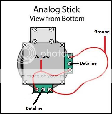
The middle pin on each pot is the respective data line. The pins on either side are either ground or 3.3v. You'll need to figure out what is what (multimeter helps) and just reconnect your lifted pin/trace thing.
 
With your pinout guide as reference, once I figure out which pin is what, can I connect it to any ground and any 3.3v pin on the chip (since the chip has multiple pins for each)?

Anyone with an opened up controller and a multimeter care to save me 20 bucks on a multimeter and tell me which pin is which?

I guess a multimeter is a good thing to have anyway, I hope a cheap one will do.

How would I test the pins to find out what each one does? I touch one of the probes to ground and the other to a pin on the pot?

Now it's starting to cost about as much as another working controller but at least if I can do this, I should be able to fix any controller in the future.

I just remembered, I think I can find the datasheet for the pots I have...maybe that will have the info.

Maybe not...just looks like dimensions unless I'm missing something:
http://www.produktinfo.conrad.com/d...en-3D_JOYSTICK_F_POTENTIOMETER_O_SCHALTER.pdf
 
wiring_stick_2_engadget_howto-1.jpg
 
You are my hero sir.....this forum is hallowed ground. Thanks thanks thanks...going to give it a shot.
 
Back
Top