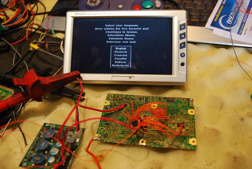
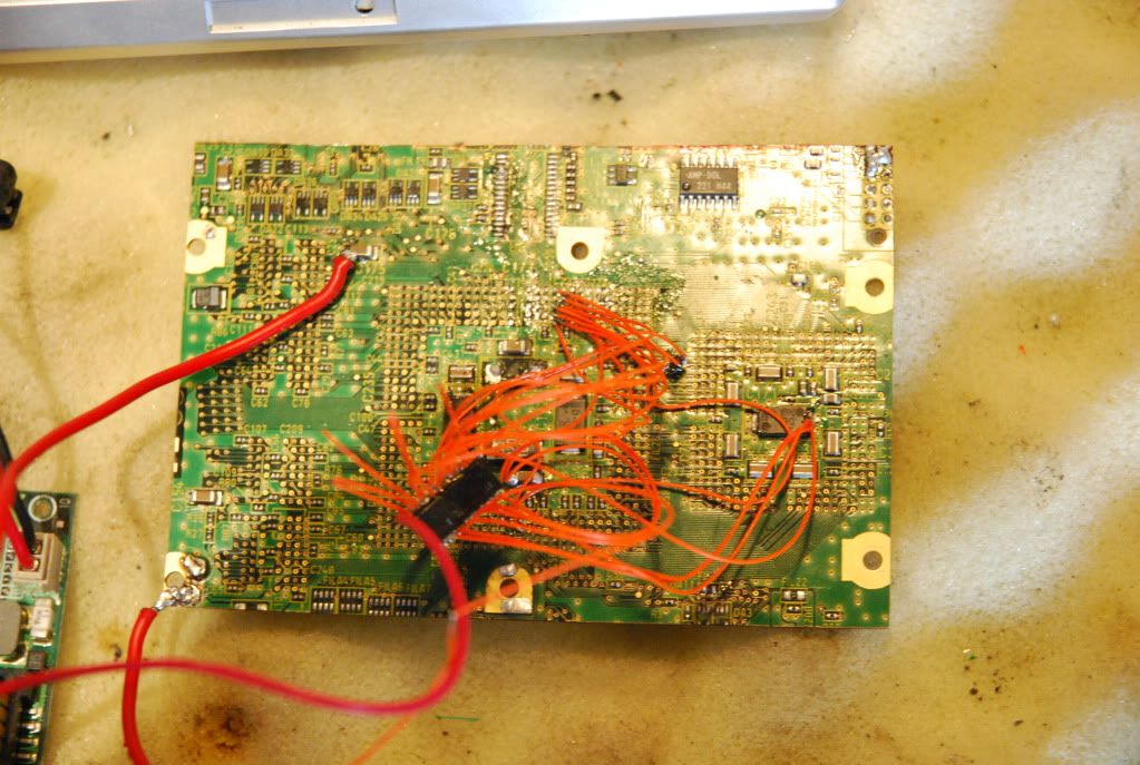
The definitive GC motherboard trimming guide

If I get anymore rev C mobo's in the lots I buy off e-bay I will certainly sacrifice them to the portable gods. I'm pretty certain the controller/memcard side can be trimmed the same. We may be able to cut the whole built in regulator off also and just use Zenloc's custom.
 
kill00man said:
@zenloc (and Techknott) : you are crazy ! Relocating the ARAM chip or/and the AV chip is just crazyness,

Last week I did an AV chip swap out. Its not as bad as you would think. Useful if you fry your AV chip, which has happened to me once or twice (either sound or video will just stop working, but the cube will still function).

@Ashen, I have thought about removing all the regulator stuff on the rev C boards. It looks like a hopeless mess which is why I gave up quickly, but I wish you luck :)

@Zenloc, are you saying we don't need that annoying black chip on the corner near the ARAM? I hate that lil thing and would love to slice it off.

great work guys. I should prolly just sit back and let the big boys do their thing. You three have far surpassed mobo man.

:awesome:
 
Relocated the AV chip. Its probably not worth the hassle as there are a compulsory 20 wires needed. Anything less and you get intermittent issues like black/white and distortion and relocating the aram will almost certainly result in timing issues.
DSC_0144.jpg

DSC_0146.jpg
 
Techknott, you are the king of soldering :eek:
Well I was also thinking about how to trim more and I think there is no point in going further... All the unnecessary part of the mobo have already been taken off, so all we can do is relocating the components... It would be less wide but more long (or worse, more thick)... So anyway, it would be very hard to use a 3.5" screen (may look disproportionate) and the batteries won't fit in such a small case I think. We can use 4.3" screen as the mobo fits in a psp (thanks to zenloc), and it will look awesome ! And I dont talk about how hard would be the relocations (as Techknott said).

I also want to give a little advice to new comers, when trimming the mobo, you should start to cut the less important things first (cause they are the easier to relocate or repair in case of problem), and you may want to test your board after each cut. So I think a good order for trimming a rev A or B board is :
-Digital Out
-Analog Out (you may want to use a custom audio amp)
-Power relocation (when your relocation is workig then cut the connector)
Then the hard part :
-Memcards and controller board connectors (plus the strange connectors)
Relocate the memcards and the controllers, and if you want to cut like the OMGWTF guide :
-just cut everything which is linked to memcards controllers etc :twisted:
And now:
-the DD connector

Following this you should be able to try after each cut if your board is still working fine !

EDIT: Here's 3 little pics, first one is basic, juste to explain to newbies what is the AV side and the controller/etc side. The second one (more or less, not accurate at all) shows to what desserve each part of the mobo, and the last one is my final cut (I think).
110420044553581796.png

110420044653490858.png
(what is written in big letters are the most important things on the mobo)

110420044900980321.png

Please remember, if you're using zenloc's power regulator, you don't have/don't need the thermal security.
If you see a problem, just tell me !
 
Tchay said:
. I should prolly just sit back and let the big boys do their thing. You three have far surpassed mobo man.

Tchay :/ .... The only reason I can make any of these cuts with confidence is because of the work you and Zenloc did prior to me showing up here. Don't quit on me now!

Tchay said:
@Ashen, I have thought about removing all the regulator stuff on the rev C boards. It looks like a hopeless mess which is why I gave up quickly, but I wish you luck :)

We'll see when I get my hands on another rev C if its even worth the effort. Really at this point I think we should be satisfied with what we have all found... These boards can be made really tiny! The only reason to put the effort into a rev C mobo now would just be to have a more complete guide for everyone.
 
Ashen, I have no access to any kind of Gamecube other than Rev. C's, of which I have about 6. And so it may also be helpful to people without a Rev A or B. And all Rev Cs. are IPL 1.2 so no one using one has to worry about WiiKey compatibility.
 
I'll sand a motherboard as soon as I break one, I don't really want to sacrifice one right now, but If I break one/find a broken one, then I will. My current portable doesn't need any cuts because... I can't say right now, but I will soon.
 
Did the OMGWTF cut on the controller side.

Turns on and works, but after wiring up the black chip, controller still won't respond.

Now I used a black chip from another boards and it was bottom one (of the 2). I made sure it was oriented right too. Maybe its more picky than I thought....Not sure about wire length either.

Zenloc, did you use the same black chip from your board or was it from another board? I figure the chips would all be the same.
 
Tchay, did you make sure it's was the right way round? If you look closely, there is a grey stripe down one side and a number on it(315 I think). There are two different types on the board and only one will work.
 
techknott said:
Tchay, did you make sure it's was the right way round? If you look closely, there is a grey stripe down one side and a number on it(315 I think). There are two different types on the board and only one will work.

Okay, then I used the wrong one. I'll try it tomorrow or when I have more patience :p

Wire length shouldn't be an issue right?
 
Wired up my OMGWTF cut board with power and video just to see if it would turn on. After much poking around I've gotten it to power up and display video correctly. I have not wired up anything else as of yet but I'm working on the controller connection as we speak.

The point that Techknott has said that you can bridge to ground to re-enable video needs a 2.4k resistor between it and ground to get video to display properly (on NTSC boards at least). I cut thru this resistor and tried just bridging pin 15 to ground but it gives me crapola video output. I didnt have a 2.4k resistor handy so I used a 1.8k one, video is much better but not perfect with this, I'll have to get a 2.4k one. Also the composite video output from this chip is on pin 9 not pin 7 like Techknott has shown in his diagram. I will update this info in the first post when I have time.
 
Also, could someone try testing digital output? Anyone with a component cable.......

I have one and can do testing once I get my screen. But it would be nice to know if those cuts affect the component out a all and if progressive will still run with a fully slimmed board.
 
Tchay said:
Also, could someone try testing digital output? Anyone with a component cable.......

I have one and can do testing once I get my screen. But it would be nice to know if those cuts affect the component out a all and if progressive will still run with a fully slimmed board.
I guess you mean without the filtering caps?

I have a component chip, but I'm currently out of solder :cry4:
Will have more this tuesday I hope.
 
Abb_eliten said:
Tchay said:
Also, could someone try testing digital output? Anyone with a component cable.......

I have one and can do testing once I get my screen. But it would be nice to know if those cuts affect the component out a all and if progressive will still run with a fully slimmed board.
I guess you mean without the filtering caps?

I have a component chip, but I'm currently out of solder :cry4:
Will have more this tuesday I hope.

yes exactly. :)
 
Tchay, Component should still work. While I was poking about trying to get video to work correctly I hooked up component out to all the RGB lines and got static images. which tells me all those data lines are still working proper.

Also I wired up everything so far besides the DD to my OMGWTF cut and everything seems to be working. Update once i get DD hooked up :D
 
Just wired video and power on my new mobo (looking similar to the OMGWTF guide) and have a video issue..
The video looks blurry and kind of crappy... I first thought it was due to a GND too small but I m now sure that it is not the problem (I put 3 cables)...
Does anybody encountered that ? I think that the 2.42 kOhms resistor on the AV chip's 15 pin may be the problem as I didn t replace it..
 
Haha, its no problem man. I've been neglecting updating this post as I've been trying to get my first GC Fusion done. Now that it is I'll spend a bit of time updating the OMG cut section with the newest relevant info. I think this "Video resistor issue" only effects NTSC boards. I need confirmation on this though.
 
Back
Top