bentomo
Frequent Poster
Now that it's easy to put in an expansion pak if you have the right tools by replacing the ram chips. All we have left to do is make our own jumper pak. Now lets get started.
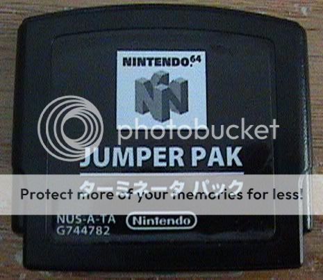
Here is an official nintendo jumper pak, revision 3.
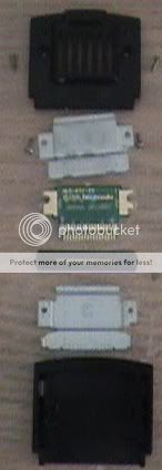
Here's it disassembled.
Here's the front.
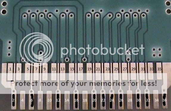
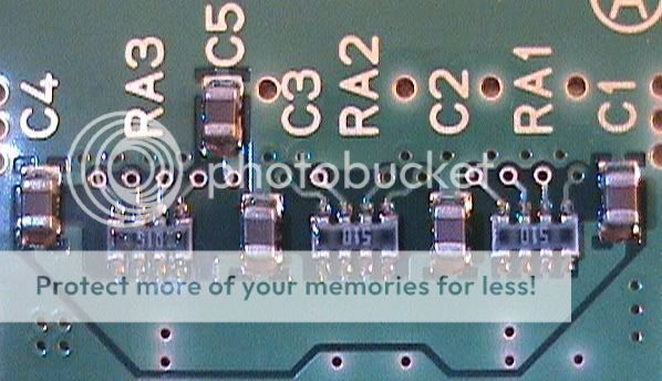
Here's a closeup of the traces. Black lines are ground.
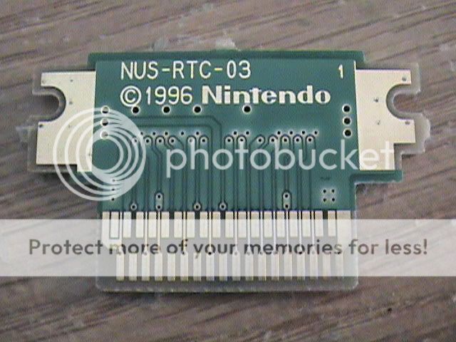
Here's the back.
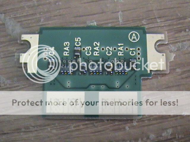
Here are the back components.
Here is a N64 without the jumper pak slot.
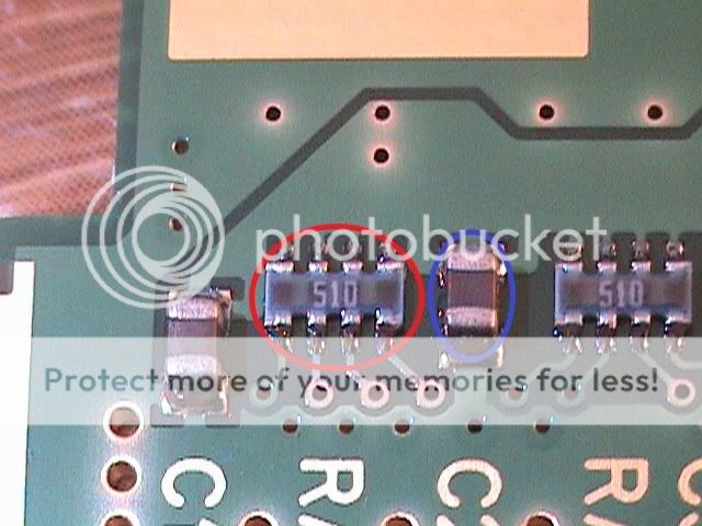
Here are the two kinds of components. Red circle is the resistor pack, each one measuring 51 ohms. Blue circle is a surface mount capacitor, 3.3 microfarads.
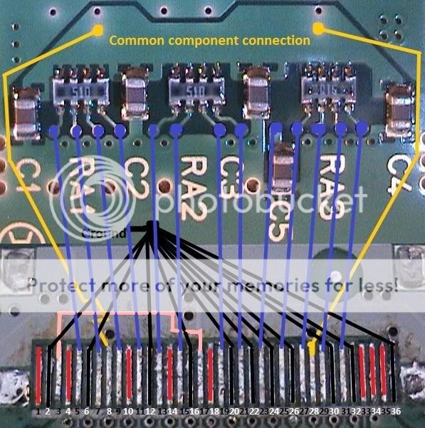
Here's the wiring diagram I made.
RED: Pins are not connected to anything
Black: pins are ground, remember to tie the ground to all the correct ends of the components
gold: common component connection between all components (except capacitor 5) and two pins
BLUE: pins connected to components
pink. two pins need to be bridged.
LATER REVISIONS OF THE JUMPER PAK DON'T HAVE THE 5TH CAPACITOR, SO PIN 23 CAN BE LEFT UNCONNECTED TO ANYTHING
Here are some notes I took while doing this.
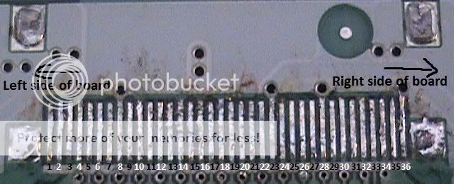
1. Copper pins pattern starts high on the left and ends low on the right.
2. 9 pins are not connected: 1, 4, 10, 14, 18, 23, 33, 34, 35
3. 11 pins are ground: 2, 6, 12, 16, 20, 22, 24, 26, 30, 32, 36
4. 2 pins are connected to eachother: 3, 17
5. 2 pins are connected to common component connection: 8, 28
What are the benefits of this?
Even if you relocate the jumper pak, a little bit still sticks out of the front of the n64. Also if the values are figured out then you can make your own jumper pak. And knowing what pins you can bridge like ground and what aren't connected are nice too.
Please point out any mistakes.
This has been confirmed working by several members of the forum.
Here is an official nintendo jumper pak, revision 3.
Here's it disassembled.
Here's the front.
Here's a closeup of the traces. Black lines are ground.
Here's the back.
Here are the back components.
Here is a N64 without the jumper pak slot.
Here are the two kinds of components. Red circle is the resistor pack, each one measuring 51 ohms. Blue circle is a surface mount capacitor, 3.3 microfarads.
Here's the wiring diagram I made.
RED: Pins are not connected to anything
Black: pins are ground, remember to tie the ground to all the correct ends of the components
gold: common component connection between all components (except capacitor 5) and two pins
BLUE: pins connected to components
pink. two pins need to be bridged.
LATER REVISIONS OF THE JUMPER PAK DON'T HAVE THE 5TH CAPACITOR, SO PIN 23 CAN BE LEFT UNCONNECTED TO ANYTHING
Here are some notes I took while doing this.
1. Copper pins pattern starts high on the left and ends low on the right.
2. 9 pins are not connected: 1, 4, 10, 14, 18, 23, 33, 34, 35
3. 11 pins are ground: 2, 6, 12, 16, 20, 22, 24, 26, 30, 32, 36
4. 2 pins are connected to eachother: 3, 17
5. 2 pins are connected to common component connection: 8, 28
What are the benefits of this?
Even if you relocate the jumper pak, a little bit still sticks out of the front of the n64. Also if the values are figured out then you can make your own jumper pak. And knowing what pins you can bridge like ground and what aren't connected are nice too.
Please point out any mistakes.
This has been confirmed working by several members of the forum.


