from now on I will post all new findings here
Mon Mar 23, 2015
after giving it a bit of further thought, the Blue and Purple tracks are probably not as Important as all the others, because even though most of them are in line with the BIOS, they are also the raw game Data lines of the main system. this tells me that the BIOS is loaded on the exact same BUS as the raw game Data, which the I/OP sorts out, almost like a traffic light
CODERS!!! WE NEED CODERS!!! if we could find a way to inject the game Data from an ISO, in the form and format that the CPU would receive it from the I/OP, as it is read from a Disc... we would have native, full speed playback
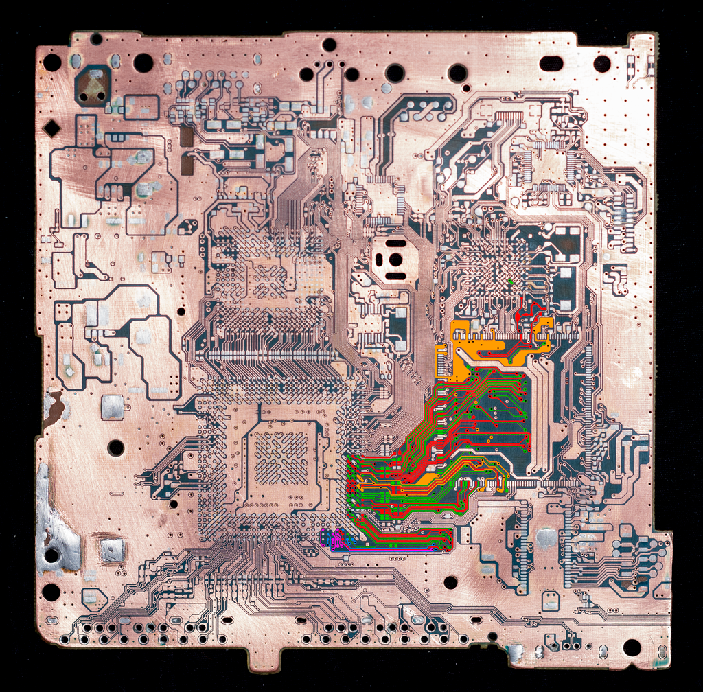
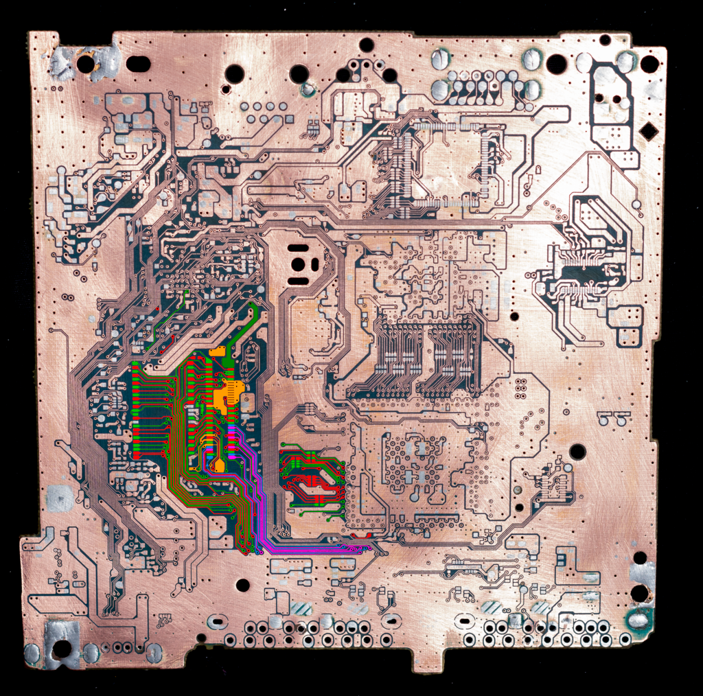
Sun Mar 22, 2015
been a while since I posted an update here, and even after all this time I really only have one thing to report.. but it could be big
you'll notice that I started from a fresh slate and made a whole new set of tracings. some plot first though: has anyone heard of the HD Pro? for those who haven't, its a mod that uses the code injection abilities of the Modbo 4.0 to load games from an HDD. the trouble is that it isn't great for speed, not much different than USB loading through OPL from what I've learned
anyway this mod injects the code into the CPU through the BIOS lines used by the Modbo, which is why it's so inherently slow. well I was looking at that 40 pin footprint next to the BIOS chip, and aside from having all 10 of the Modbo BIOS lines, it includes every single Data line on the BIOS chip, some GND, some VCC, and last but not least, 11 completely unused Data lines (Blue and Purple) which go directly into the CPU
obviously exploiting these points would require quite a bit of coding experience similar to what it takes to make a GDEMU, or a PSIO, or even a WiiKey Fusion (for Gamecube), but I was able to find a component that would fit the footprint, so we'll see what happens
http://www.digikey.ca/product-detail/en ... ND/4895053
if absolutely nothing else, this could be used to great effect to load alternate BIOS images, but its worth a look
Mon Mar 09, 2015
Just one this time, I've traced both the Y, and CX Modbo 4.0 points and found alternate points on the back side of the board (decreased latency). the new CX is right next to the BIOS, its been marked with a light violet, and the new Y is just above the BIOS, marked in red
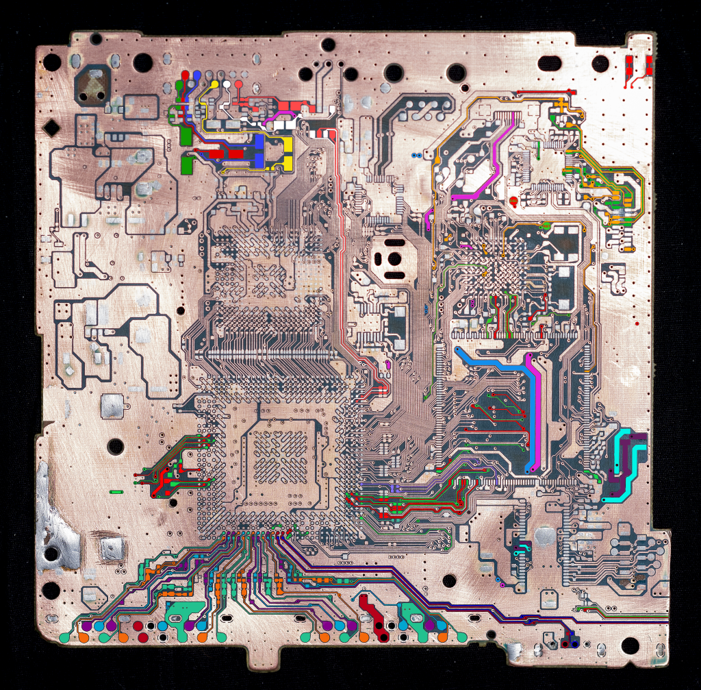
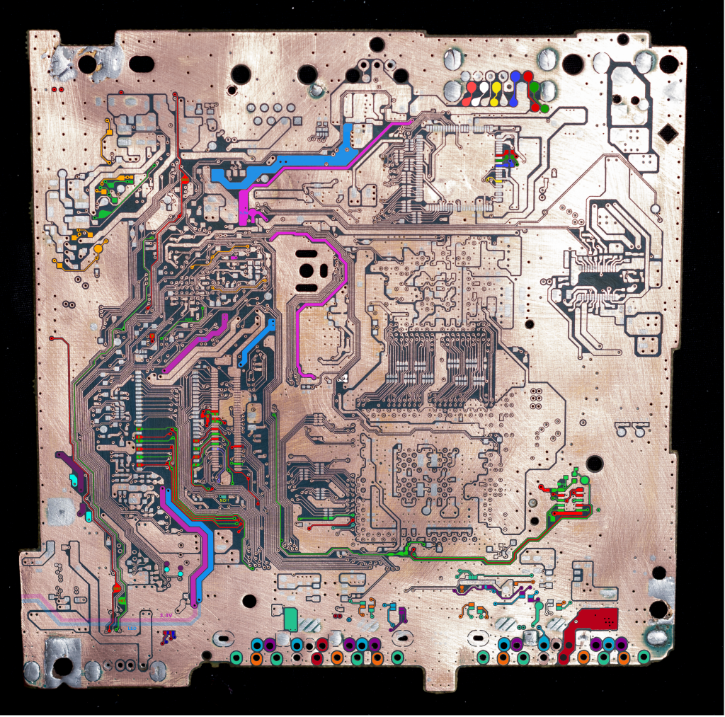
the inherit loss of quality makes all of this difficult to discern, I need a way to upload them in original resolution..
Previous Updates
*Sat Mar 07, 2015*
this update is rather large, it comes after I've revealed about 9% of the sub copper, but through it I have been able to trace the DVD Drive almost completely. I've also traced the A/V out back through the filters to their respective sources, I have not yet been able to determine if they will function correctly without the filters. there are also 2 new points that can be used for disc lid and reset, near the DVD laser cable
one thing I want to call attention to this time around is the red and green tracings on the top side of the board, coming out the left side of the CPU. they may turn out to be nothing, but they could possibly be used as another method of playing backups. there's certainly enough pins for say.. an SD card? food for thought
*Fri Mar 06, 2015*
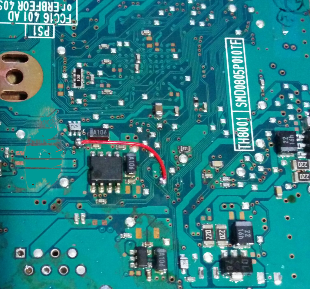
this is just an improved method for closing the disc lid, it uses the original power bus, and is very easy to solder. the single wire closes it all the time, and a switch between the two points lets it open/close
*Tue Mar 03, 2015*
one thing I want to point out is the Teal pad marked "NO", this has been the widely accepted method for activating the disc drive, but the other side of the board (which I will post soon) shows that this pad is linked directly to the CPU and I/O processor, this could be potentially harmful, or at the very least may cause long term performance issues, because every time you close the switch, you create a voltage drop. the tracks highlighted and water colored Magenta 3.3V, are the original power bus used by the system for this function
Mon Mar 23, 2015
after giving it a bit of further thought, the Blue and Purple tracks are probably not as Important as all the others, because even though most of them are in line with the BIOS, they are also the raw game Data lines of the main system. this tells me that the BIOS is loaded on the exact same BUS as the raw game Data, which the I/OP sorts out, almost like a traffic light
CODERS!!! WE NEED CODERS!!! if we could find a way to inject the game Data from an ISO, in the form and format that the CPU would receive it from the I/OP, as it is read from a Disc... we would have native, full speed playback


Sun Mar 22, 2015
been a while since I posted an update here, and even after all this time I really only have one thing to report.. but it could be big
you'll notice that I started from a fresh slate and made a whole new set of tracings. some plot first though: has anyone heard of the HD Pro? for those who haven't, its a mod that uses the code injection abilities of the Modbo 4.0 to load games from an HDD. the trouble is that it isn't great for speed, not much different than USB loading through OPL from what I've learned
anyway this mod injects the code into the CPU through the BIOS lines used by the Modbo, which is why it's so inherently slow. well I was looking at that 40 pin footprint next to the BIOS chip, and aside from having all 10 of the Modbo BIOS lines, it includes every single Data line on the BIOS chip, some GND, some VCC, and last but not least, 11 completely unused Data lines (Blue and Purple) which go directly into the CPU
obviously exploiting these points would require quite a bit of coding experience similar to what it takes to make a GDEMU, or a PSIO, or even a WiiKey Fusion (for Gamecube), but I was able to find a component that would fit the footprint, so we'll see what happens
http://www.digikey.ca/product-detail/en ... ND/4895053
if absolutely nothing else, this could be used to great effect to load alternate BIOS images, but its worth a look
Mon Mar 09, 2015
Just one this time, I've traced both the Y, and CX Modbo 4.0 points and found alternate points on the back side of the board (decreased latency). the new CX is right next to the BIOS, its been marked with a light violet, and the new Y is just above the BIOS, marked in red


the inherit loss of quality makes all of this difficult to discern, I need a way to upload them in original resolution..
Previous Updates
*Sat Mar 07, 2015*
this update is rather large, it comes after I've revealed about 9% of the sub copper, but through it I have been able to trace the DVD Drive almost completely. I've also traced the A/V out back through the filters to their respective sources, I have not yet been able to determine if they will function correctly without the filters. there are also 2 new points that can be used for disc lid and reset, near the DVD laser cable
one thing I want to call attention to this time around is the red and green tracings on the top side of the board, coming out the left side of the CPU. they may turn out to be nothing, but they could possibly be used as another method of playing backups. there's certainly enough pins for say.. an SD card? food for thought
*Fri Mar 06, 2015*
this is just an improved method for closing the disc lid, it uses the original power bus, and is very easy to solder. the single wire closes it all the time, and a switch between the two points lets it open/close

*Tue Mar 03, 2015*
one thing I want to point out is the Teal pad marked "NO", this has been the widely accepted method for activating the disc drive, but the other side of the board (which I will post soon) shows that this pad is linked directly to the CPU and I/O processor, this could be potentially harmful, or at the very least may cause long term performance issues, because every time you close the switch, you create a voltage drop. the tracks highlighted and water colored Magenta 3.3V, are the original power bus used by the system for this function

