dmnchief001
Member
First post, so please answer with care. 
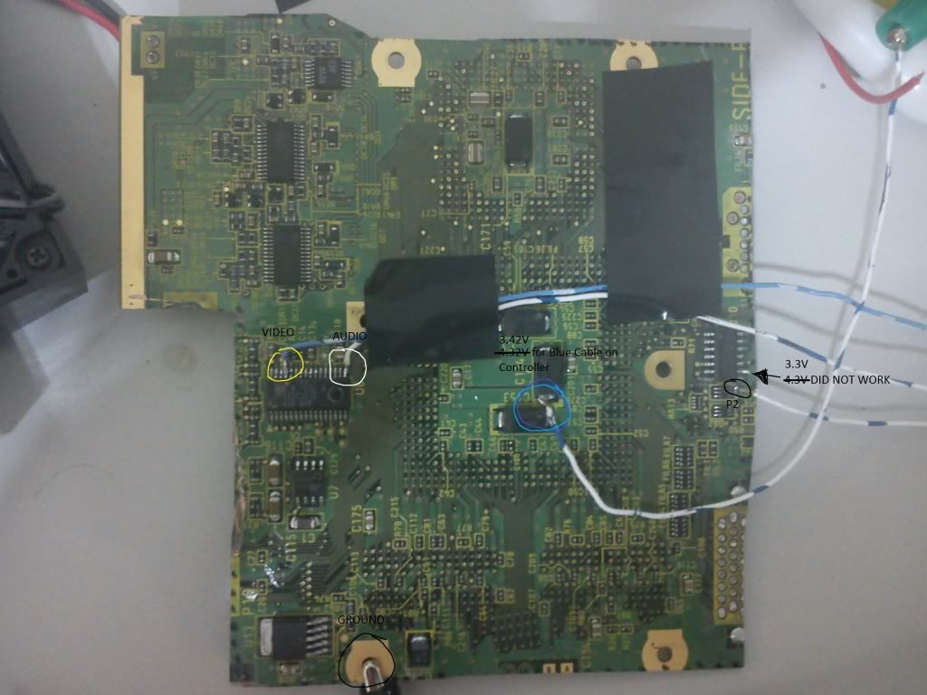
I have a Rev. C motherboard. I am testing my video and controller pins before I cut the board.
I have audio and video working, and now I am testing the controller.
I only connected these three controller wires to the pins shown in viewtopic.php?f=36&t=9329 :
Red: 3.43V data line
Ground: only the center unshielded cable (I originally had the main shielding and the center unshielded cable connected and I don't see a difference.)
Blue: 3.43V Power Supply
So here's the problem. When I had all three wires connected, the GCP did not boot. When I disconnected the ground from the controller, the GCP booted, but the controller doesn't work (duh).
Now here's the interesting part. When I have only the red and ground cables connected, the GCP boots and the controller works fine at the main screen (analog and button presses).
My questions are:
Has anyone else had this issue?
If it ain't broke, should I fix it?
I think my issue is solved as the controller is working in the main screen, but will the controller continue to work in games?
Finally:
The composite video pin for me was pin FOUR instead of pin EIGHT shown in viewtopic.php?f=36&t=9329 .

