You are using an out of date browser. It may not display this or other websites correctly.
You should upgrade or use an alternative browser.
You should upgrade or use an alternative browser.
Naimlessones GCsp
- Thread starter naimlessone
- Start date
RedmagnusX
Active Member
I actually got those thumb sticks from an Android bluetooth controller called The Steelseries Wireless Bluetooth controller. They're actually much better than the Vita thumb sticks and offer much better range than 3ds sliders. The pinout is the same as a standard thumb stick (X, Y, 3.3v, ground).
You can buy the controller here.
http://www.amazon.com/SteelSeries-Wirel ... 9P4C3SJQYZ
You can buy the controller here.
http://www.amazon.com/SteelSeries-Wirel ... 9P4C3SJQYZ
RedmagnusX
Active Member
Sure thing. Here you go.

Now to explain it a little bit, it's essentially wired up to a simple DPST switch. It's wired up so that when it's switched in one direction, the P1 controller is set to the internal controller and the component chip is switched to VGA mode, which is how it's wired to the internal screen. When it's switched to the opposite direction, the P1 data line is going to the P1 data pin on my serial connector, which when plugged into the handheld, goes to pin 2 on the p1 port on my hub. Meanwhile, the component chip is switched over to component mode (Pin 12 to ground).
If you're not using component, it's as simple as substituting the pin 12 line on the diagram with your Composite video signal source line. Then all you have to do is wire up the corresponding pins on the diagram to your internal video and external video connector.
trevor403
Member
If you need a really nice set of gamecube ports with pins cleanly exposed i'd suggest using the gamecube controller ports off of a Wii. You can find a really nice cheap broken Wii for anything south of $10. They have raised port endings where as the gamecubes controller ports are thinner lower and just covered by the gray faceplate. Also with the gamecube's ports the pinout comes straight down from the port and you need something like prefboard to support the port shielding. With the Wii ports the the shielding is supported by the plastic of the ports on a a right angle, also the pins come down at a right angle so it's just a better wiring configuration in my opinion.
naimlessone
Active Member
Thank you guys for your ideas and inputs on this. I'll keep them in mind. I've been really busy lately, not so much with the portable, but with life. I have, however, been trying tho come up with a way to use the trigger slots from the GC controllers on this as the Wii U pad triggers were to tight to implement the dual-tact method and also fit the analog sticks. No pictures yet as there hasn't been much progress besides cutting out for the USB 3.0 slot for the hub (I had already cut it out and planned for this red, but am keeping the serial port idea in mind for the next one.) Hopefully more progress by this weekend, but for now its slow rolling.
RedmagnusX
Active Member
You can do what I did for the dual tact method, fill the L and R buttons with epoxy/bondo and then bore them out a bit to accommodate the tact switches. It takes a bit of precision, but it works really well.
naimlessone
Active Member
I may still do that with GC triggers as I have already cut out one side to fit one in. I think if i find the smallest tacts I can find that will still give a decent range that I can do that on a future one. I'm working on my voltage regs right now. Have two done, should have them set tonight before bed.
RedmagnusX
Active Member
naimlessone said:I may still do that with GC triggers as I have already cut out one side to fit one in. I think if i find the smallest tacts I can find that will still give a decent range that I can do that on a future one. I'm working on my voltage regs right now. Have two done, should have them set tonight before bed.
Good stuff man. Keep it up.
naimlessone
Active Member
Small update...
Finished the voltage regs up tonight. Also made up some ABS cement for the first time over the past two days and I think it turned out well. Used some of it to bond the ag-85 case back to the Wii U gamepad back along with one of the two triggers. Now i'm letting the abs cement set up, tho it seems to dry up pretty fast, at least to the touch. It was almost like a thin pudding lol. I think it will be dry enough tomorrow to continue some work on the case, getting the trigger pieces closed up as there are some small gaps around them still that I need to build up. It will be very tight where the analog sticks and triggers meet however, so I'll be working on figuring that out as well. Anyways...
PICS!
case work
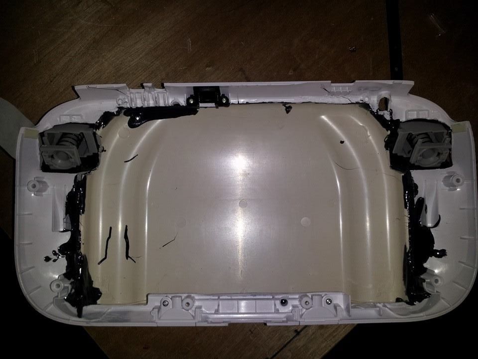
Still need to cut out for the headphone jack, av out, and SD slots as well as the vents for the fan and exhaust. Slow and steady!
Voltage Regs
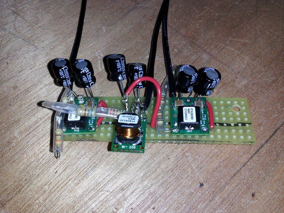
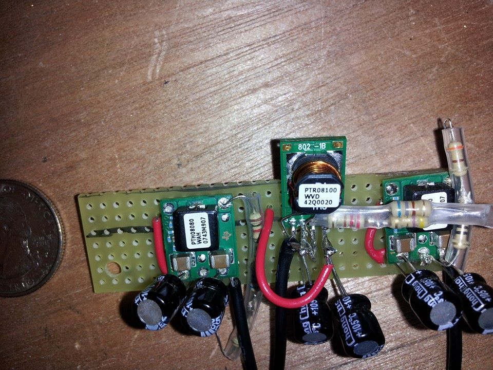
Finished the voltage regs up tonight. Also made up some ABS cement for the first time over the past two days and I think it turned out well. Used some of it to bond the ag-85 case back to the Wii U gamepad back along with one of the two triggers. Now i'm letting the abs cement set up, tho it seems to dry up pretty fast, at least to the touch. It was almost like a thin pudding lol. I think it will be dry enough tomorrow to continue some work on the case, getting the trigger pieces closed up as there are some small gaps around them still that I need to build up. It will be very tight where the analog sticks and triggers meet however, so I'll be working on figuring that out as well. Anyways...
PICS!
case work
Still need to cut out for the headphone jack, av out, and SD slots as well as the vents for the fan and exhaust. Slow and steady!
Voltage Regs
Shank
Formerly Known As Dyxlesci
Looks nice. Mind posting more pictures of the triggers? Im curious about how you fit those in there neatly, and how comfortable the rear case is. Im having trouble with that part.
Beware the triggers though. I put mine in and it seemed to fit but once I put the circuit board and membrane for the front face buttons, it wouldn't close. I had to sacrifice analog functionality to get it all working. I was using a wii u hard case instead so I had more room to work with as well. Not saying its impossible, just plan for more clearance than you think you will need.
Beware the triggers though. I put mine in and it seemed to fit but once I put the circuit board and membrane for the front face buttons, it wouldn't close. I had to sacrifice analog functionality to get it all working. I was using a wii u hard case instead so I had more room to work with as well. Not saying its impossible, just plan for more clearance than you think you will need.
naimlessone
Active Member
It is really tight right now. But I haven't trimmed the GC triggers at all yet so i'm hoping that will give me enough room to squeeze in with the analog sticks. I have a few different analogs though from ps2, xbox 360, wii pro controllers and the original 3rd part cube controllers to take a look at what's the smallest I can get in there. If I can get the dual tacts to mount inside of the triggers and remove the spring part of them I will have plenty of space for any of the analogs mentioned. No pics yet, but I will post some when I get to that part.
The rear part of the case is actually quite comfortable. The AG-85 back isn't too big at all, only issue will be sanding the putty I have put along the seams of the two halves. I'll post some pics of what I mean tomorrow. I'm working on a MSpaint wiring diagram of the whole thing right now before I go to bed. Hoping Mega starts taking orders again soon so I can get some trimming done as well.
The rear part of the case is actually quite comfortable. The AG-85 back isn't too big at all, only issue will be sanding the putty I have put along the seams of the two halves. I'll post some pics of what I mean tomorrow. I'm working on a MSpaint wiring diagram of the whole thing right now before I go to bed. Hoping Mega starts taking orders again soon so I can get some trimming done as well.
naimlessone
Active Member
I know this is kind of small to see, not sure how to get it bigger, but if you ctrl-+ a few times it's easier to read. I started drawing this the other day in pencil with a straight edge. Went back in with paint to make it clearer what had to go where.
Still missing a few little things, like the connections to the Wasp, but other than that, I believe this should work.
WARNING! I am not 100% sure that this diagram is correct. To the best of my knowledge it is, but this being my first GCp, this is a work in progress.
EDIT: fixed, cleaned up and added some points in the diagram, with switching headphone jack wiring points. Obviously the WASP gets either wired to an ffc cable to the board or MEGAdrive adapter so I didn't show that because there are multiple ways to do that. And just a note, you do not need to take 7.4-14.8 volts to the controller hub at all. I am doing this as I intend to put put LEDs inside of it as the case I'm using for the controller hub is a clear case as I've shown in previous posts.
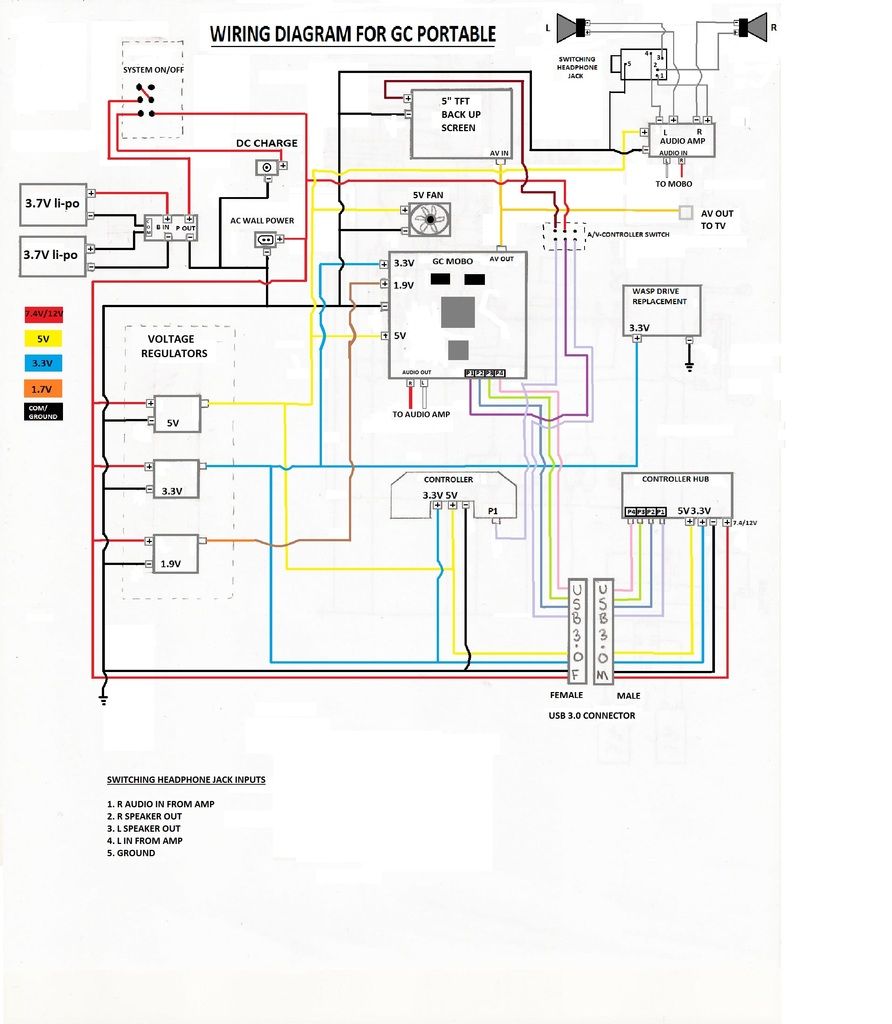
I hope that this diagram helps clear up some stuff that I've seen multiple people post questions about. I will be following this verbatim unless I find something that I did wrong, in which I will be sure to fix the picture to show.
Still missing a few little things, like the connections to the Wasp, but other than that, I believe this should work.
WARNING! I am not 100% sure that this diagram is correct. To the best of my knowledge it is, but this being my first GCp, this is a work in progress.
EDIT: fixed, cleaned up and added some points in the diagram, with switching headphone jack wiring points. Obviously the WASP gets either wired to an ffc cable to the board or MEGAdrive adapter so I didn't show that because there are multiple ways to do that. And just a note, you do not need to take 7.4-14.8 volts to the controller hub at all. I am doing this as I intend to put put LEDs inside of it as the case I'm using for the controller hub is a clear case as I've shown in previous posts.
I hope that this diagram helps clear up some stuff that I've seen multiple people post questions about. I will be following this verbatim unless I find something that I did wrong, in which I will be sure to fix the picture to show.
Shank
Formerly Known As Dyxlesci
naimlessone said:I know this is kind of small to see, not sure how to get it bigger, but if you ctrl-+ a few times it's easier to read. I started drawing this the other day in pencil with a straight edge. Went back in with paint to make it clearer what had to go where.
Still missing a few little things, like the connections to the Wasp, but other than that, I believe this should work.
Thats a clean, very clear, and detailed diagram, especially for a ms paint one. This could be useful as a diagram for new people.
I agree with bush; we need someone to consolidate information and threads into an organized way for us to quickly access resources
RedmagnusX
Active Member
Nice diagram. I particularly like how you plan to wire up your P1/video out switch. That's how I would have done it were it not for the need to have a switch for the component chip in my portable. It totally works for Composite though.
naimlessone
Active Member
Do you mean Tchays sound fix? I know I need to get 5-12v to the mobo for the audio amp and 5v to the actual Iluv digital amplifier for the sound, as well as the R and L from the mobo to the audio amp. I'm gonna edit that diagram to show the latter. Been pretty busy lately and taking a long weekend out of state this weekend so there won't be much more progress unfortunately.
EDIT: I edited the picture to show the 5v to the mobo for the audio amp
also, where can I find an adapter for a composite female video out, similar to this in the green circle:
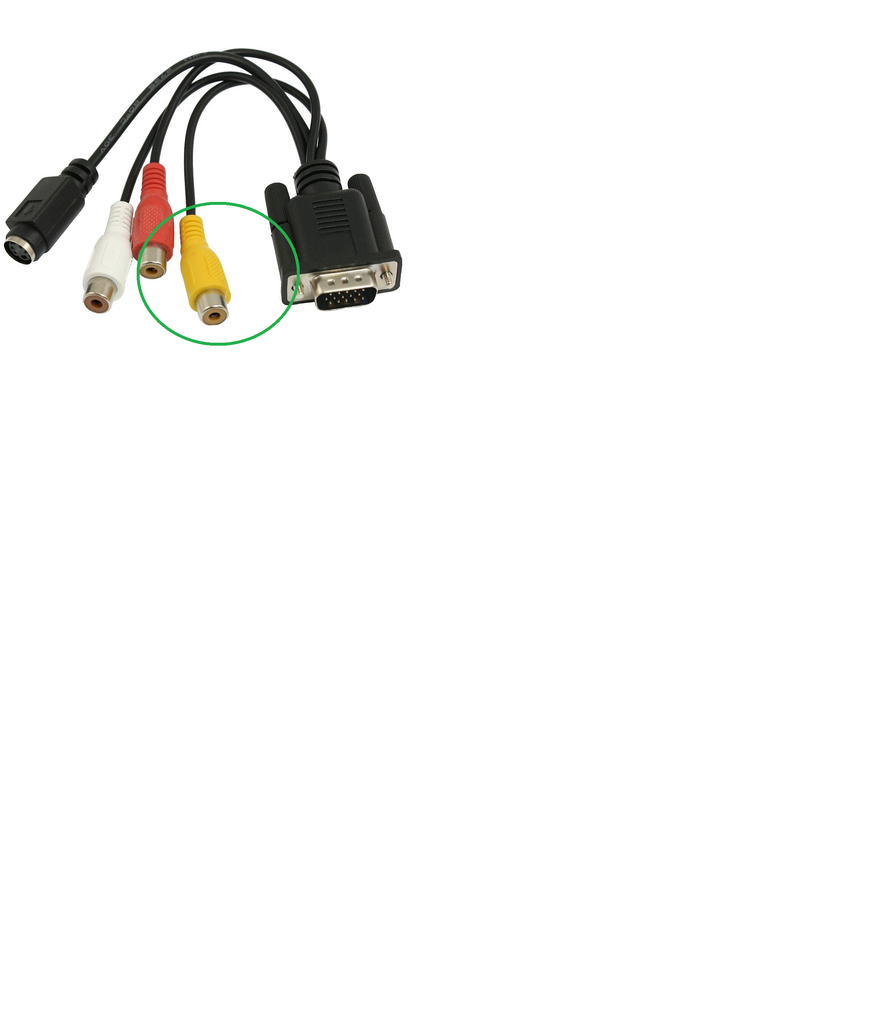
Do I need to buy something like that and scavenge the part or is there someplace I can get that to attach to my board? A link If you do come across one would be fantastic.
EDIT: I edited the picture to show the 5v to the mobo for the audio amp
also, where can I find an adapter for a composite female video out, similar to this in the green circle:
Do I need to buy something like that and scavenge the part or is there someplace I can get that to attach to my board? A link If you do come across one would be fantastic.
RedmagnusX
Active Member
The screen you're using should have come with a female RCA plug. If not, you can get them from a few things like old VCRs, RCA extension cables and other old composite video based electronics. Every screen I've ever used has come with one or two though.