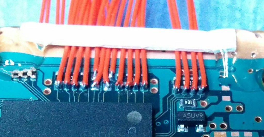
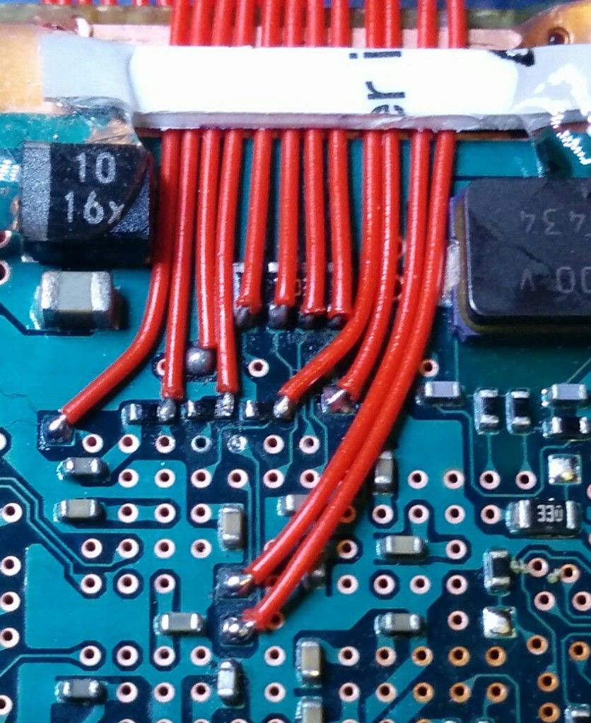
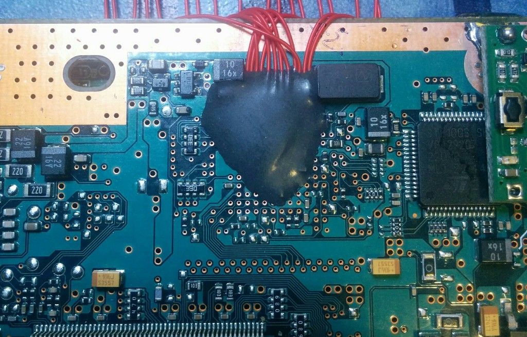
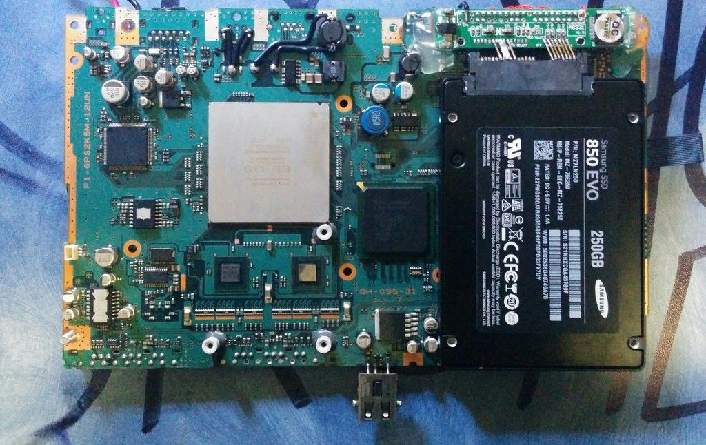
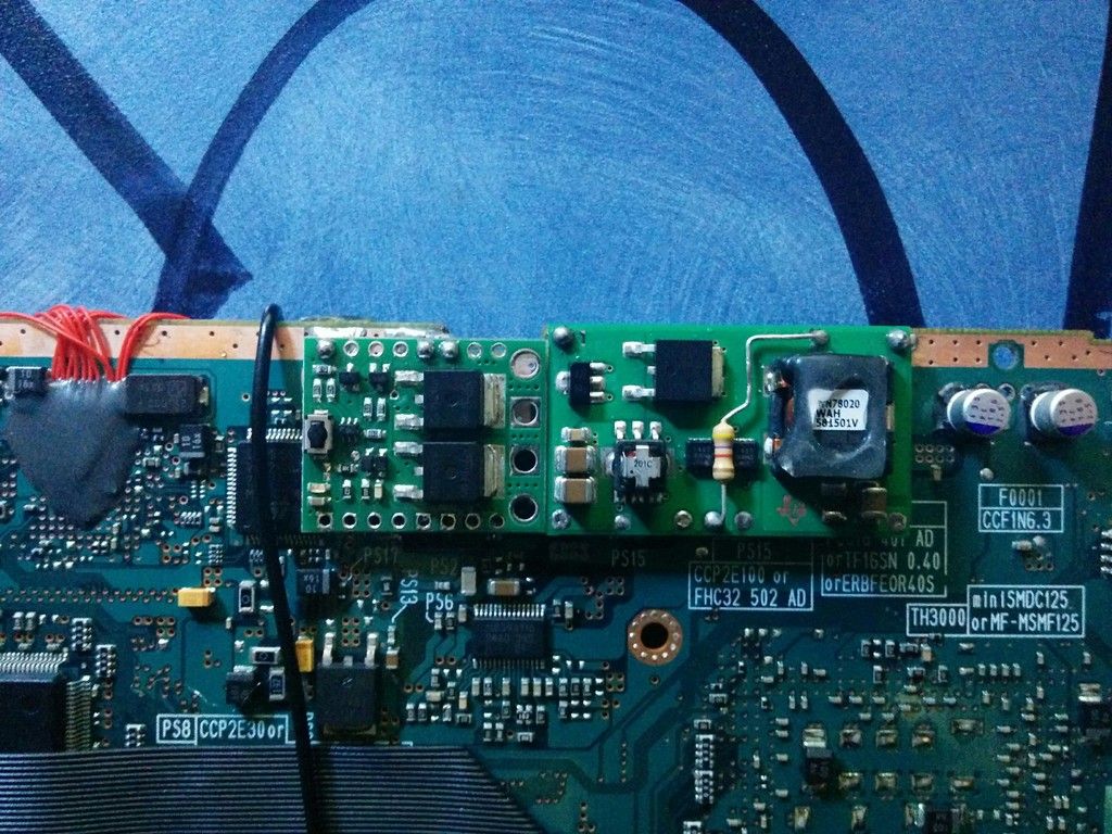
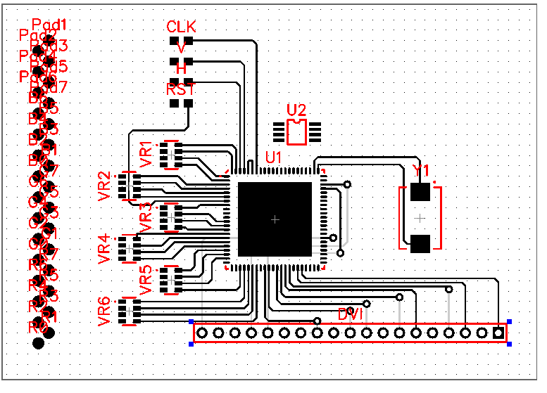
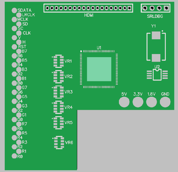
Okay, cards on the table, I bollocked up my board, and subsequently kicked myself in same. But I wouldn't be the scientist I like to think I am (picturing myself swanning about in a lab coat with Bunsen burners the only visible source of illumination) if I didn't turn this into an opportunity, because I've ordered and fast shipped a new PS2 motherboard, but this time with a slightly more DIY twist to the HDD, as suggested by @AKuHAK.
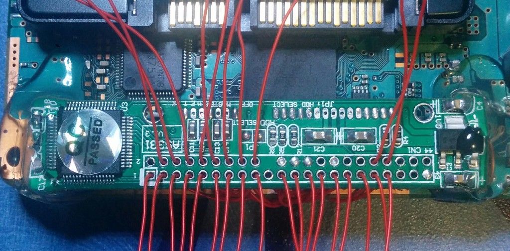
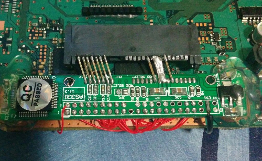
I'm using this board as the SATA interface:
http://www.aliexpress.com/item/UESH-Hot ... 18400_6150
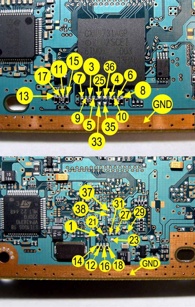
Basically I'm just going to solder my 30awg kynar to the points (I forgot about my l33t modchip skillz), label each wire with tape and felt tip, test the connection with the pins still in, then remove them, clean the holes, push each numbered wire up through it's corresponding hole, lay the board flat, pull the wires tight (they having been pre secured with JB weld), secure the board (also probably with JB weld), and solder each wire at length. Kynar is brilliant for that, if you heat it and agitate it with the tip of a soldering iron with a bit of solder on the end, and flux on the hole, you get a perfect connection at perfect length. Then all you do is either wriggle or cut the wires off at board level and that's it.
Anyway on the subject of soldering the HDD points, and the opportunity I mentioned above, the opportunity is RESEARCH!! and I've already formulated a theory;
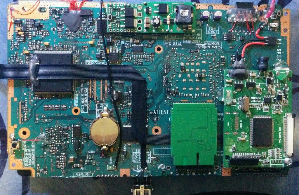
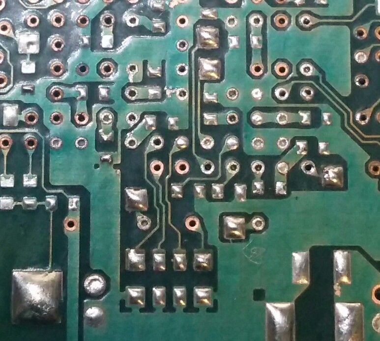
I took out the heat gun and cleaned a fair bit of the ICs off the board, then came to a bit of a wondering; Could I simply remove the resistors on the board to make it easier to solder the points?
Surely the only reason the HDD mod works is because you provide the 19 otherwise grounded signals with a path of less resistance to follow and subsequently communicate with a drive, so if I had my system patched to boot FMCB from said HDD, is there any reason I couldn't do this?
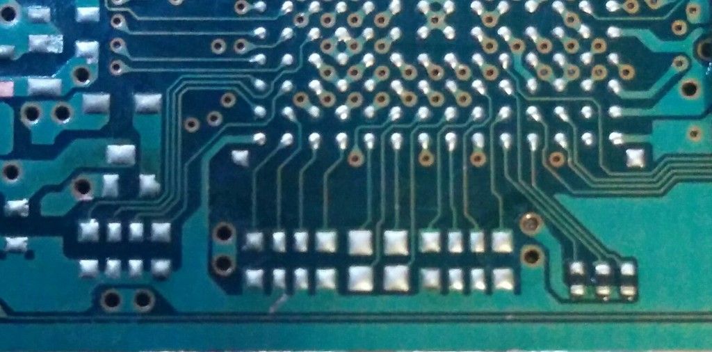
Actually by the same reasoning, and in the case that this won't work without the resistors, couldn't I just get a bunch of through hole resistors (I know the values) and solder them to ground on the converter board? Thereby making the soldering easier and preserving the electrical characteristics of the board?
Debate in the comments below!!
I'm using this board as the SATA interface:
http://www.aliexpress.com/item/UESH-Hot ... 18400_6150
Basically I'm just going to solder my 30awg kynar to the points (I forgot about my l33t modchip skillz), label each wire with tape and felt tip, test the connection with the pins still in, then remove them, clean the holes, push each numbered wire up through it's corresponding hole, lay the board flat, pull the wires tight (they having been pre secured with JB weld), secure the board (also probably with JB weld), and solder each wire at length. Kynar is brilliant for that, if you heat it and agitate it with the tip of a soldering iron with a bit of solder on the end, and flux on the hole, you get a perfect connection at perfect length. Then all you do is either wriggle or cut the wires off at board level and that's it.
Anyway on the subject of soldering the HDD points, and the opportunity I mentioned above, the opportunity is RESEARCH!! and I've already formulated a theory;
I took out the heat gun and cleaned a fair bit of the ICs off the board, then came to a bit of a wondering; Could I simply remove the resistors on the board to make it easier to solder the points?
Surely the only reason the HDD mod works is because you provide the 19 otherwise grounded signals with a path of less resistance to follow and subsequently communicate with a drive, so if I had my system patched to boot FMCB from said HDD, is there any reason I couldn't do this?


Actually by the same reasoning, and in the case that this won't work without the resistors, couldn't I just get a bunch of through hole resistors (I know the values) and solder them to ground on the converter board? Thereby making the soldering easier and preserving the electrical characteristics of the board?
Debate in the comments below!!

