BlueLemming
Member
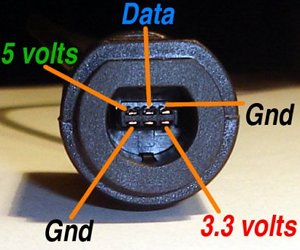
I know there's a diagram for the gamecube, but it's different on the Wii and I can't seem to find one. I tried to figure it out myself using my home-made continuity tester. I took apart my controller, plugged it in and tried testing the pins but every pin acted as connected. So I dunno if it's my tester or what, but I don't know how else I'd figure out the diagram myself.
Closest I've seen is from Ben Heck's documentation on his Wii laptop.

Although he still doesn't specify which pin is which. Just how to solder the ports back on with only 4 connections, although that is helpful.
Closest I've seen is from Ben Heck's documentation on his Wii laptop.

Although he still doesn't specify which pin is which. Just how to solder the ports back on with only 4 connections, although that is helpful.


