Apparently I am VERY easily distracted. I was keeping this n64 board around for testing my screens... but having it open was just too much temptation.
Plans:
3x 3.7V 5Ah packs from batteryspace w/ charger and protection circuit left over from my GCp
4.3" amazon screen
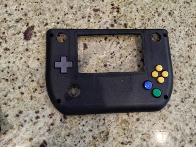
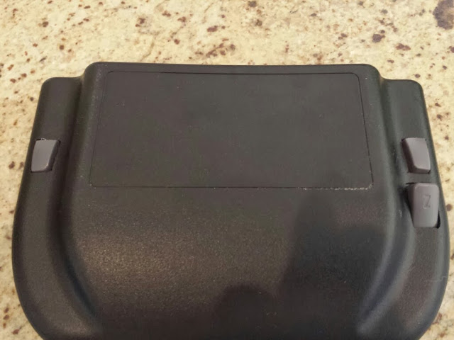
Polycase AG-85
Everdrive64 inside (may scrap this idea- a second everdrive may not arrive in time for the build off and I don't want to risk the one I have now)
10k ohm Wheel Pot
Headphone jack (switchable)
Heat sinks
Consumables:
Wire, 30g kynar and 22g solid from RS
Diamond Dremel wheels Harbor Freight
Solder and iron
Epoxy/CA Superglue: HF or Hobby Lobby, big ole pile of different options
Hot Glue/gun
Test leads
Desoldering wick (best invention EVER)
Stepping bits, drill bits
Sand paper: course through fine
Large particle board for portable workspace safety
Safety glasses, gloves
Hand tools
Drill Press, the poor man’s CNC
Work so far: (total time spent ~4 hrs)
Removed from case per this guide
Tested video out, power in with stock connectors still attached just in case
Expansion pack successfully folded per this guide
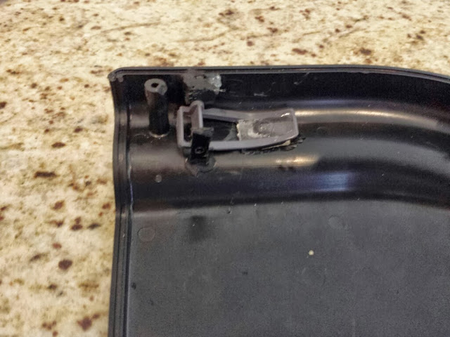
Cart relocated per this guide

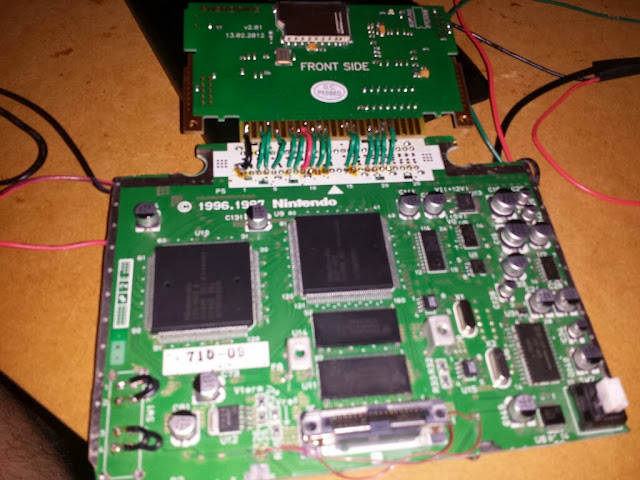
Trimmed mostly matching this guide. I made a few changes to where power was pulled, I ran it to the pins that used to be for the power switch instead of scratching the traces. In hindsight, I wouldn't have cut the power traces above the cart pins... it was just rework bridging the power per the relocation guide and didn't save me any room. I guess I should've read that a 9th time before cutting. 3.3v in to pin 6, 7.4 v in to pin 8, v to C13 pad , r audio to c122, l audio to c23
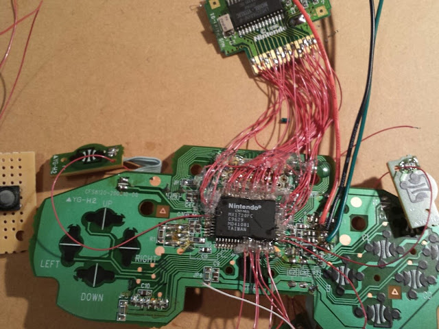
Controller wiring:
p1.1 to c104 pad, 1.2 fil2 pad, 1.3 gnd
p2.1 to fil3 2.2 to fil4 2.3 to gnd
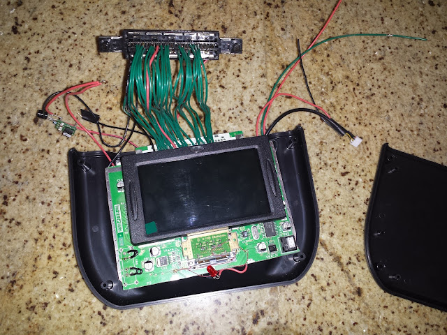
Video is using shielded cable that came with the screen, grounded. Retained stock plug for the video board, soldered to the 30 gauge wires for quick disconnect.

Test fit inside the case post trim. I will need to redo my relocation... too much stiff wire. I should've used WAY more flexible wire, so note to self (and other modders) don't use heavy gauge solid core wire for your relocation. Soldering it was a breeze, but it's REALLY hard to adjust where the slot goes with out breaking wires off the mobo. I'll flip the mobo upside down in the case and it will need to just be a short 90 degree relocation.
Still to do:
Redo relocation with short wires
Remove the guts from a stock controller, relocate buttons/sticks
Wire controller to n64, wire controller port for 2 player
Cut case and make mounting brackets for boards/batteries
Plans:
3x 3.7V 5Ah packs from batteryspace w/ charger and protection circuit left over from my GCp
4.3" amazon screen
Polycase AG-85
Everdrive64 inside (may scrap this idea- a second everdrive may not arrive in time for the build off and I don't want to risk the one I have now)
10k ohm Wheel Pot
Headphone jack (switchable)
Heat sinks
Consumables:
Wire, 30g kynar and 22g solid from RS
Diamond Dremel wheels Harbor Freight
Solder and iron
Epoxy/CA Superglue: HF or Hobby Lobby, big ole pile of different options
Hot Glue/gun
Test leads
Desoldering wick (best invention EVER)
Stepping bits, drill bits
Sand paper: course through fine
Large particle board for portable workspace safety
Safety glasses, gloves
Hand tools
Drill Press, the poor man’s CNC
Work so far: (total time spent ~4 hrs)
Removed from case per this guide
Tested video out, power in with stock connectors still attached just in case
Expansion pack successfully folded per this guide
Cart relocated per this guide
Trimmed mostly matching this guide. I made a few changes to where power was pulled, I ran it to the pins that used to be for the power switch instead of scratching the traces. In hindsight, I wouldn't have cut the power traces above the cart pins... it was just rework bridging the power per the relocation guide and didn't save me any room. I guess I should've read that a 9th time before cutting. 3.3v in to pin 6, 7.4 v in to pin 8, v to C13 pad , r audio to c122, l audio to c23
Controller wiring:
p1.1 to c104 pad, 1.2 fil2 pad, 1.3 gnd
p2.1 to fil3 2.2 to fil4 2.3 to gnd
Video is using shielded cable that came with the screen, grounded. Retained stock plug for the video board, soldered to the 30 gauge wires for quick disconnect.
Test fit inside the case post trim. I will need to redo my relocation... too much stiff wire. I should've used WAY more flexible wire, so note to self (and other modders) don't use heavy gauge solid core wire for your relocation. Soldering it was a breeze, but it's REALLY hard to adjust where the slot goes with out breaking wires off the mobo. I'll flip the mobo upside down in the case and it will need to just be a short 90 degree relocation.
Still to do:
Redo relocation with short wires
Remove the guts from a stock controller, relocate buttons/sticks
Wire controller to n64, wire controller port for 2 player
Cut case and make mounting brackets for boards/batteries