RedmagnusX
Active Member
Hello all,
I decided to make a guide for an audio amplifier that I've used in a few of my projects now. Following this simple guide should have your audio amplifier prepped and ready to be installed in your project.
The amplifier in this guide comes from these HDMX GOXL Portable Speakers. They can be purchased at your local Walmart for $9.99.


These speakers are very easy to open up. Simply unzip the case and pry open the top half that contains the speakers and amplifier. Once pried open, there will be 4 screws that need to be removed.
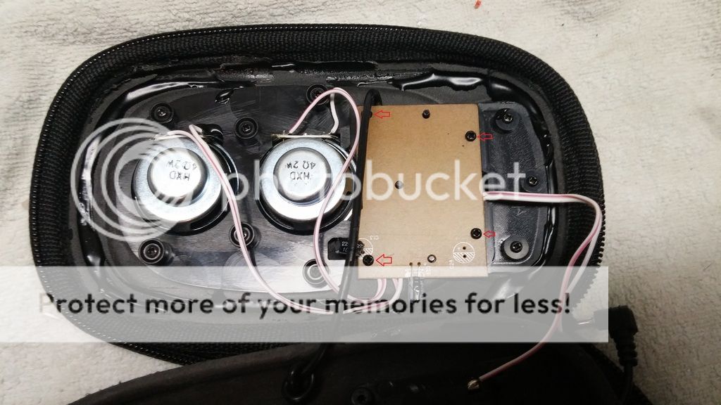
Once inside, you will have to desolder all the connections to free the amplifier.
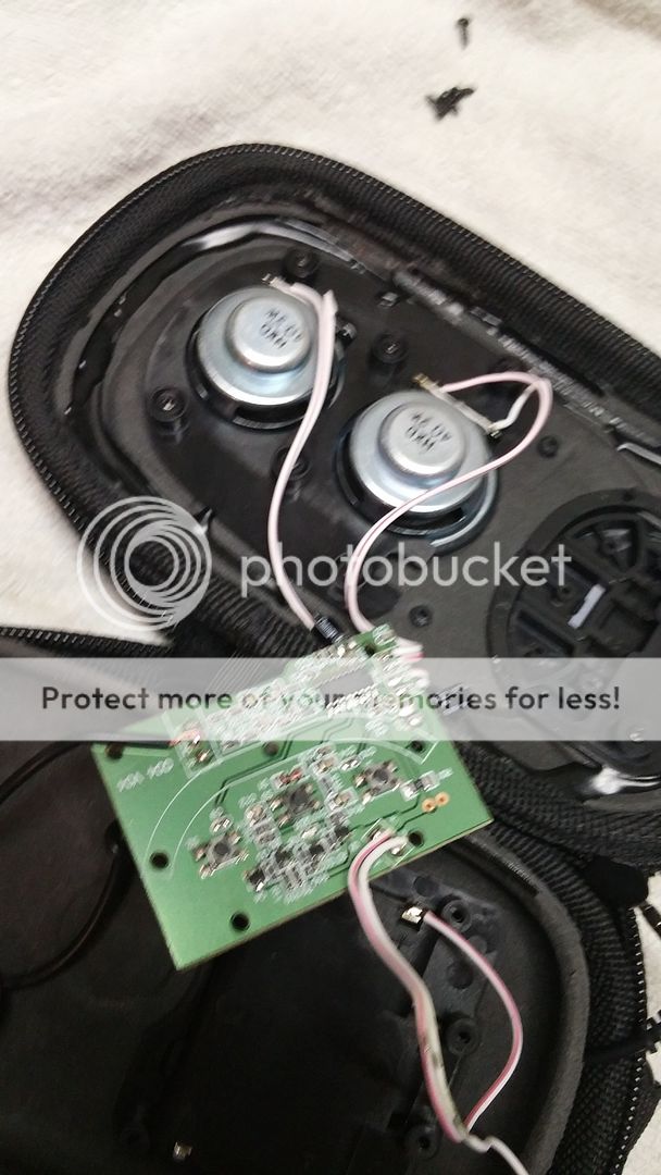
Once free, the amplifier should look like this.
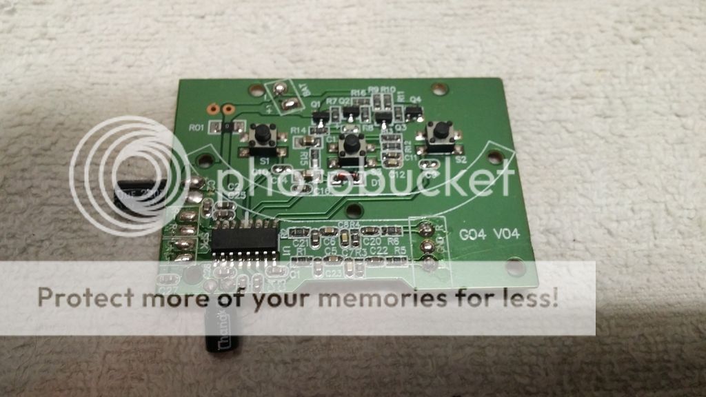
Okay, now it's time to get down to the nitty gritty. You'll notice 3 tact switches on the amplifier. One is for power and the other two are for volume up and volume down respectively. Desolder them for now and put them aside. Now, there's a capacitor that can be removed as it will no longer be needed due to the alternate wiring for power that we will be using. It is the one circled in the picture below.

Once all those components are removed, your board should look something like the picture below. Now, we can trim the board a bit to make some space. Just follow the line I've drawn in the picture below.

Once cut, your board should look like what's pictured below. I've labeled all the relocation points in the picture as well. It's important to note the relocation for the power input. With that relocation, the audio amplifier will turn on when given power, therefore bypassing the power button.


