DarkWing
Member
This step by step guide will go through preparing the board so that it is ready to wire all the different parts.
We are not go to go through wiring the parts to the board as there is quite a few variable depending of which parts, e.g. screen, power source, you choose to use.
LIke any project always do your research before attempting a PS2 portable, try to figure out which screen, power source, case, controller you will use along with the tools/ supplies needed to build it and the space available in your case to fit everything.
You will go through the following steps
1 - Removing the first lid sensor switch, only for PAL system (79002, 79003, 79004)
2 - Removing the Ethernet and Optical port
3 - Bridging the sensor lid switch, only for PAL system (79002, 79003, 79004)
4 - Removing the Memory and controller ports
5 - Removing the USB port
6 - Squaring off the board
7 - Removing the video port and DC ports
8 - Trimming other bits ( optional )
9 - The board is ready to wire up!
10 - What's next?
What you will need:
PS2 board 7900X (That's a surprise )
)
Diagonal plier
Needle-nose plier
Dremel
protective glasses
dust mask
soldering iron ( at least 40w, better to get one with temperature control )
sanding paper 40 or 80 grid
solder
soldering pump
wires
tactile switch
So lets get to it!
1 - Removing the first lid sensor switch, only for PAL system (79002, 79003, 79004)
Let start with the fun part which is breaking staff")
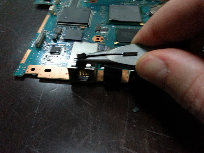
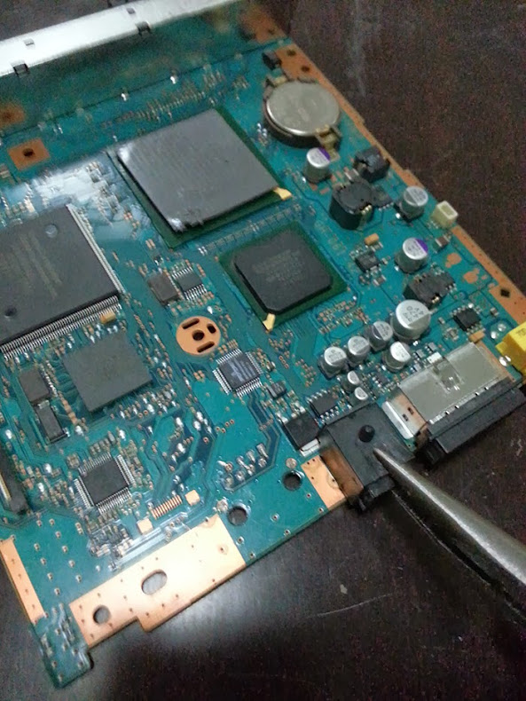
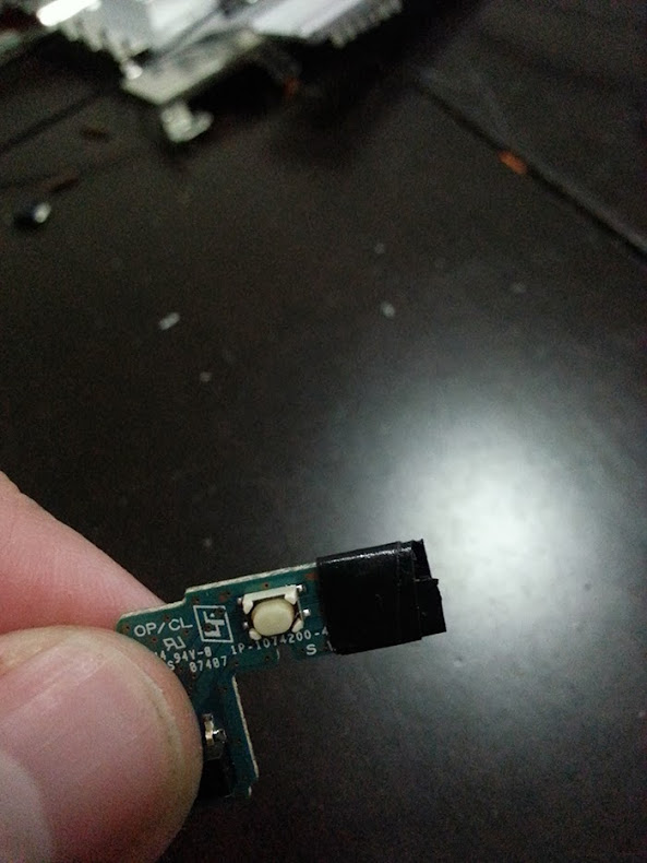
Using your Needle-nose plier you will need to remove the small black square at the top of the board next the optical drive connector.
It should come out pretty easily, the first time around mine fall of just by touching it")
Make sure that you don't have any left over piece of metal and that you can see the four solder point clearly.
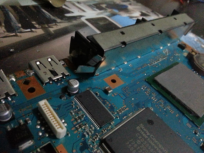
2 - Removing the Ethernet and Optical port
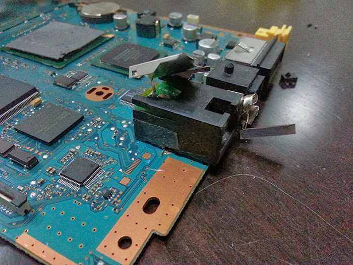
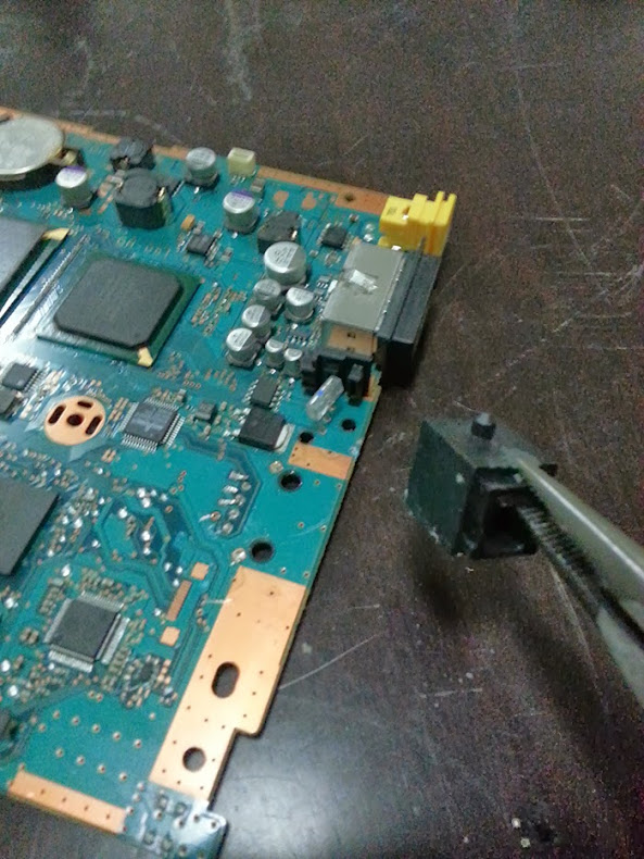
Now you will need to turn the board around and with the Needle-nose plier break the 5 plastic parts which are holding those port to the board.
Then you can start attacking the Ethernet port by bending the middle part.
Work you way to the left side by hacking through the metal (Make sure not to damage component around the port ) until you can remove it easily, don't worry if the right side is still there.
Next use the Diagonal plier and gently slide it under the port until you can cut the metallic pins.
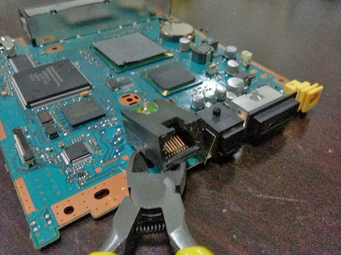
Once you have done that just cut the remaining metallic part.
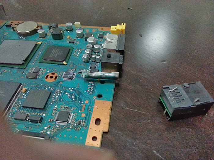
The optical drive is even easier, use the Needle-nose plier and gently turn it to the left until you can remove it.
Then just cut the remaining part.
3 - Bridging the sensor lid switch, only for PAL system (79002, 79003, 79004)
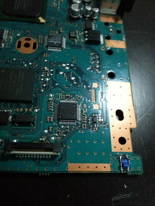
You will need to cut a small piece of wire, then remove the protective plastic on both part and separate both ends into two, twist them and prepare the wire as you would usual with solder.
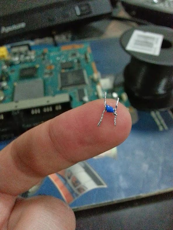
To make sure that the wire attach to the board nicely you will need to add some solder on the for points.
Then you just need to place the wire ends on top of the points and press down with your solder iron until it goes through.
Cut any part of the wire which is sticking out, you don't want to create a short when you plug it in.
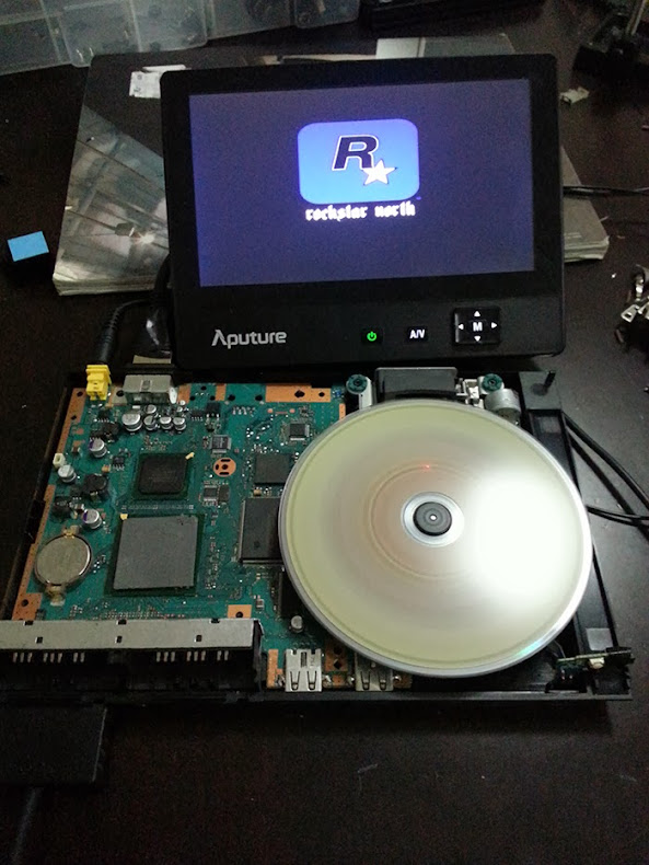
Now let's test this, put some tape on the second sensor next to the power switch.
Connect the optical drive, connect your screen/TV, plug the power, put a game in and turn it on.
If everything went to plan you should see the DVD spinning and the optical head moving with a red light.
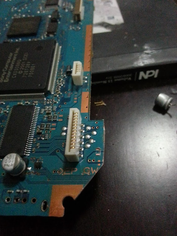
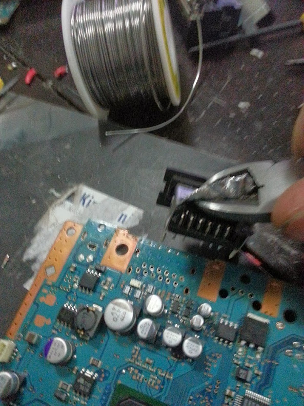
4 - Removing the Memory and controller ports
That was the trickiest part for me the first time around. Once you know what to do it become easier.
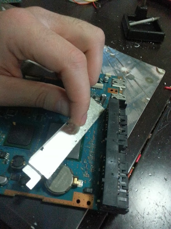
First with the Needle-nose plier bend the small metallic part on both end of the port.
Once it's done you need to gently do a backward / forward motion with the whole metallic plate until you can feel the bits which are holding it at the base snapping.
Watch out for the components next to it, you don't want to break one of those.
Next you will need to desolder the pins, that can be a bit of a pain because some pins are solder with Lead solder and other seems to be using Lead-free solder.
Solder with lead only need to be heated around 300'c to 350c to melt but Lead-free solder need around 400'c to 450'c, hence the minimum 40w soldering iron.
What you can do is to set your iron a 350 to remove all the easy one first with your solder pump,
if after 5 second of contact with the iron the solder is not melting move on to the next one.
Then once all the easy one are done set your iron at 450c and comeback to do the left over.
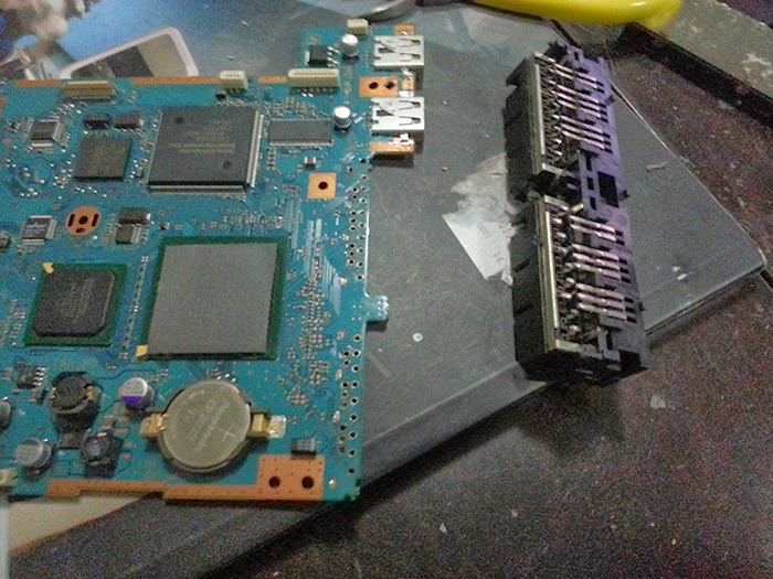
Once you have desolder the pins and you can see that they are not making contact with the board you will need to gently pull the port with a bit of left / right motion.
If you can tell that some pin are still connected you can pull the port from one hand and use the iron in the other to melt the remaining solder.
So after all that effort you should end up with a big chunk of the board removed.
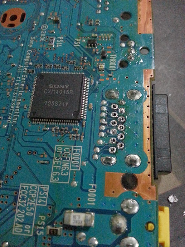
5 - Removing the USB port
Next we will remove the USB port which is the closest from the controller port. Don't worry about the second USB port it will be cut out in the next step.
So to remove it you will need to use the diagonal plier to cut the two end which are holding the port to the board.
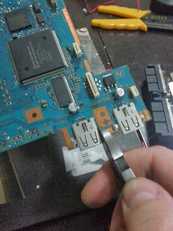
Then desolder the pins at the back and remove the port.
Again keep in mind that if one solder joint is not melting properly you may need to set you iron at 450c.
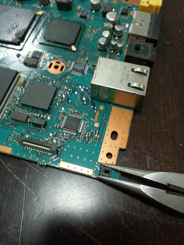
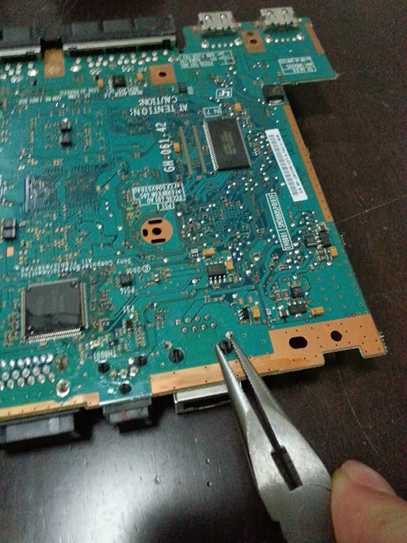
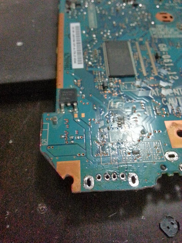
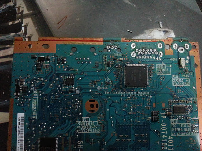
6 - Squaring off the board
Note: this step with step 7 can be done before step 4 if you wish to test the on/off tactile switch with a controller.
Now you should have only the video and DC port on the board. So the next step is to square off the little piece of the board sticking out with the second USB.
What you will need to do first is to remove the component next to optical drive connector so that you have enough space to cut it.
Then you can turn over the board an trace a line where you will cut.
You will need to watch out for the trace which are under the optical drive port.
Just use the same cutting line as the one on this picture and you should be fine.
Before anything else make sure that you are wearing your protective glasses and dust mask,
cutting the board will create a really fine dust which you don't want to breath.
Using the dremel cut just before the line to have a safety margin. once done just use some sanding paper,
40 or 80 grid should do the job, to remove any metallic trace from the edge.
7 - Removing the video port and DC ports
Same as for the controller ports you will need to remove the metallic casing first, work your way through the side and try to bend bit by bit until you can remove all of it, again make sure not to damage the part around the port.
Then moving on to the iron and desolder the pin use the same technic use for the controller port.
And remove the DC port is just a matter of setting your soldering iron to 450c and removing the solder with you soldering pump so that you can pull out the port.
8 - Trimming other bits ( optional )
Now that you have removed all the ports that leave you some room to trim the board, I wouldn't advise to cut too much from the board as the more you cut the greater is the risk to mess up something but there is a few part which can be cut safely.
The largest one would be the part that runs from the side next to the DC holes to the lid sensor switch.
Cutting this will save 4 or 5mm which can make a difference.
You can also cut the small bit sticking out which is in-between the controller port.
Final you can trim a few millimetres on the USB part from the two large solder point, they are only there to hold the USB port.
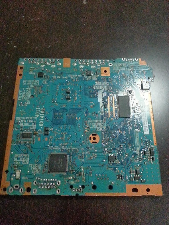
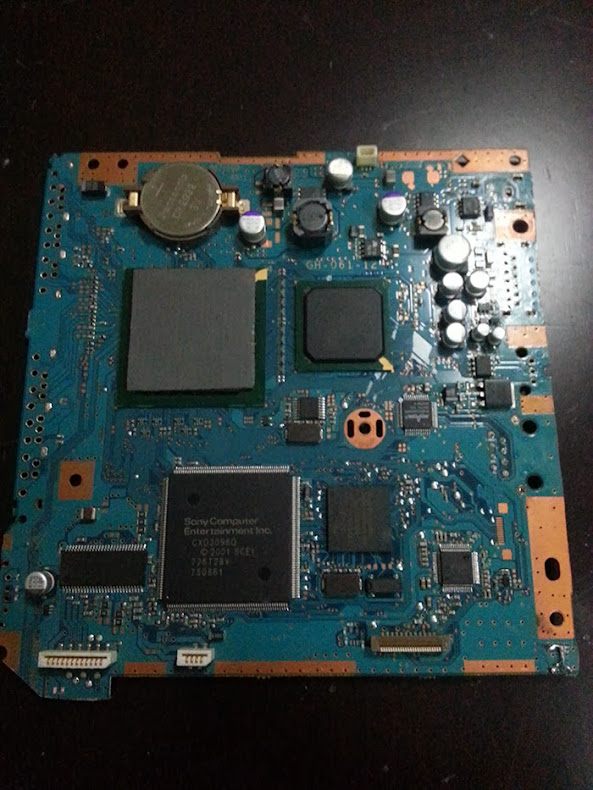
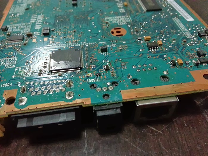
9 - The board is ready to wire up!
Now you have a nice squarish board which is relatively smaller.
Next what you will need to do is wire a tactile switch to replace the on/off button that we cut previously.
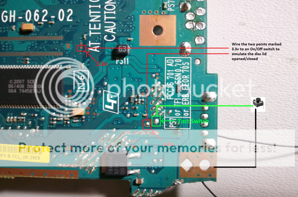
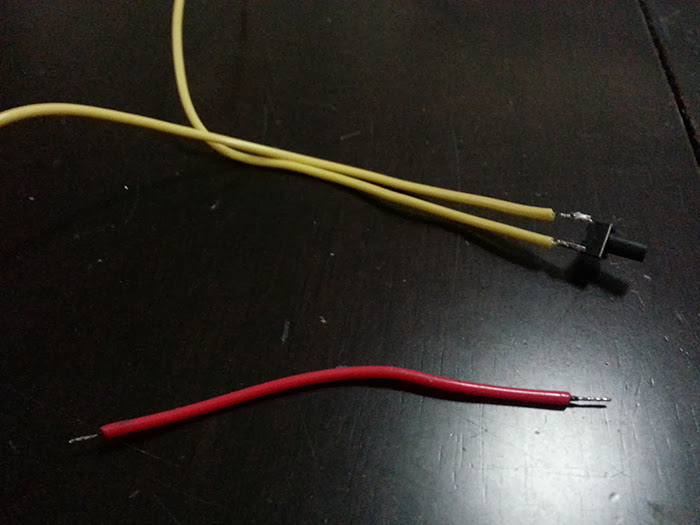
For that you will need to solder 3 wires, 2 wires will be solder to the tactile switch and 1wires will draw 3.5v from the board and direct that to the switch.
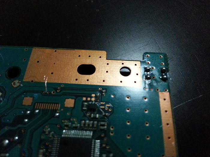
There is a few place where you can get 3.5v, for me i find it easier to get it from one of the pin hole on the second memory card as in most case you wouldn't really need a second memory card anyway.
If you wish to use the second memory card you can also get 3.5v and ground from the second controller holes.
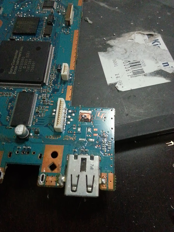
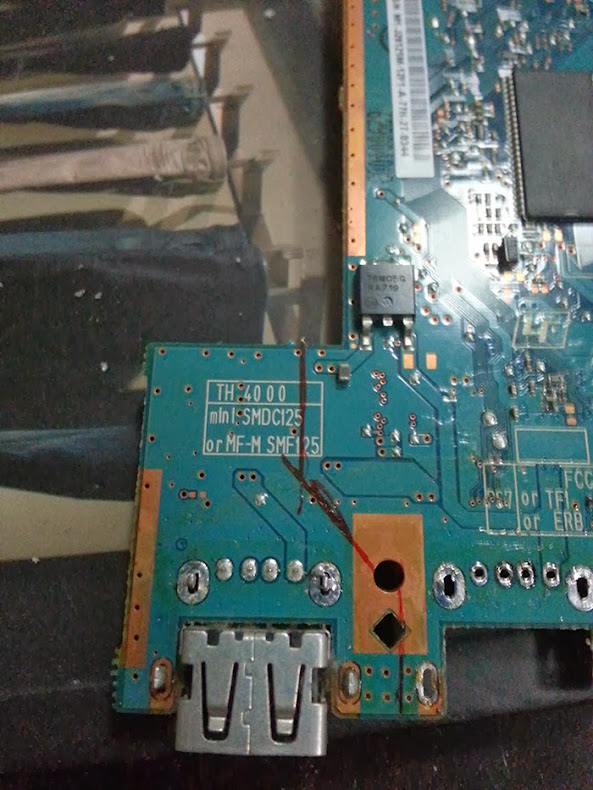
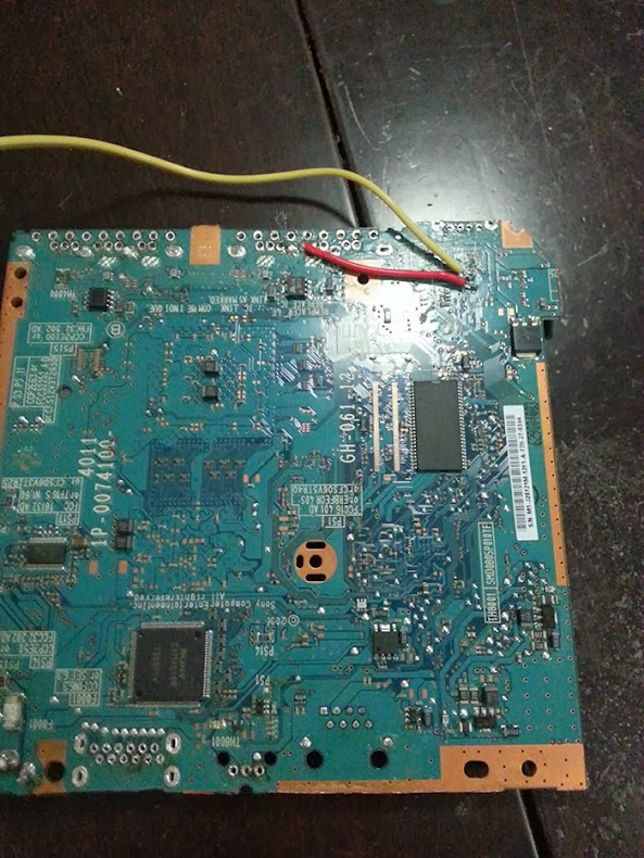
The following image shows the exact point where you should connect the wires.
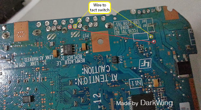
Solder one end of the smallest wire ( red wire ) to the fifth hole from the right and the other end to the point on the board.
Then you need to solder 2 wires which are connected to the tactile switch, the first one need to be solder to the ground which is the fourth hole from the right on the picture above and the second wire need to be connect to the second point on the board.
For a more precise image of the board soldering points you can check out this guide.
10 - What's next?
Well the next steps are pretty obvious.
Most likely you will need to wire the following to the board:
Power source
Battery or/and DC jack depending of your set up.
If you have a 11.1v battery you should go for a step down switching regulator to output a steady 8v to the board
or you could do this mod from hailrazer to use a 7.4 battery.
If you go for the first option make sure the regulator, on/off switch and the wires you use with the battery will be able to keep up with the volts and amp needed by the board, screen and other part that draw current.
Just to be safe i would recommend your part to be able to work with 12v 5amp, more is ok but you don't want to go lower than 4amp.
Screen
Depending of your screen there is some good guide in the reference section or online on how to mod/wire ps1 and LCD screen.
Controller
Preferably one without the carbon membrane, a third party controller is probably your best bet e.g. GameStop ps2 controller.
Memory card
You need to cut the memory to separate it from the controller port.
The best way to go about it is to use the dremel to first cut the block in two then trim the plastic until you just have the memory slot and the 2 hook on both side that hold the card. After you just need to wire the slot to the board with 8 wires.
USB port
Mostly if you want to use MC Freeboot. Wire to the board the original USB or you can use an other USB 1 / 2 port.
Keep in mind that if you use a USB 2 port it will be use by the board like a USB 1 port anyway.
DVD drive
If you wish to keep the optical drive, you will need to extend the cables.
Easiest way is to use hailraizer technic which basically sandwich the two cable together in a connector.
For that you will need the following parts from digikey:
24 pin connector
24 pin cable
12 pin connector
12 pin cable
And if you board is a PAL 79002, 79003, 79004 you will need a third cable and connector:
4 pin connector
4 pin cable
Case
Case wise it is a good idea to do the case work in parallel and to find out the position of each part in the case before wiring. Doing that will give you an idea of how long to cut your wire and help you fitting all the parts in the case.
This is the end of this guide, I hope that you have find this guide helpful and i'm looking forward to see more PS2 Portable out there.
We are not go to go through wiring the parts to the board as there is quite a few variable depending of which parts, e.g. screen, power source, you choose to use.
LIke any project always do your research before attempting a PS2 portable, try to figure out which screen, power source, case, controller you will use along with the tools/ supplies needed to build it and the space available in your case to fit everything.
You will go through the following steps
1 - Removing the first lid sensor switch, only for PAL system (79002, 79003, 79004)
2 - Removing the Ethernet and Optical port
3 - Bridging the sensor lid switch, only for PAL system (79002, 79003, 79004)
4 - Removing the Memory and controller ports
5 - Removing the USB port
6 - Squaring off the board
7 - Removing the video port and DC ports
8 - Trimming other bits ( optional )
9 - The board is ready to wire up!
10 - What's next?
What you will need:
PS2 board 7900X (That's a surprise
Diagonal plier
Needle-nose plier
Dremel
protective glasses
dust mask
soldering iron ( at least 40w, better to get one with temperature control )
sanding paper 40 or 80 grid
solder
soldering pump
wires
tactile switch
So lets get to it!
1 - Removing the first lid sensor switch, only for PAL system (79002, 79003, 79004)
Let start with the fun part which is breaking staff
Using your Needle-nose plier you will need to remove the small black square at the top of the board next the optical drive connector.
It should come out pretty easily, the first time around mine fall of just by touching it
Make sure that you don't have any left over piece of metal and that you can see the four solder point clearly.
2 - Removing the Ethernet and Optical port
Now you will need to turn the board around and with the Needle-nose plier break the 5 plastic parts which are holding those port to the board.
Then you can start attacking the Ethernet port by bending the middle part.
Work you way to the left side by hacking through the metal (Make sure not to damage component around the port ) until you can remove it easily, don't worry if the right side is still there.
Next use the Diagonal plier and gently slide it under the port until you can cut the metallic pins.
Once you have done that just cut the remaining metallic part.
The optical drive is even easier, use the Needle-nose plier and gently turn it to the left until you can remove it.
Then just cut the remaining part.
3 - Bridging the sensor lid switch, only for PAL system (79002, 79003, 79004)
You will need to cut a small piece of wire, then remove the protective plastic on both part and separate both ends into two, twist them and prepare the wire as you would usual with solder.
To make sure that the wire attach to the board nicely you will need to add some solder on the for points.
Then you just need to place the wire ends on top of the points and press down with your solder iron until it goes through.
Cut any part of the wire which is sticking out, you don't want to create a short when you plug it in.
Now let's test this, put some tape on the second sensor next to the power switch.
Connect the optical drive, connect your screen/TV, plug the power, put a game in and turn it on.
If everything went to plan you should see the DVD spinning and the optical head moving with a red light.
4 - Removing the Memory and controller ports
That was the trickiest part for me the first time around. Once you know what to do it become easier.
First with the Needle-nose plier bend the small metallic part on both end of the port.
Once it's done you need to gently do a backward / forward motion with the whole metallic plate until you can feel the bits which are holding it at the base snapping.
Watch out for the components next to it, you don't want to break one of those.
Next you will need to desolder the pins, that can be a bit of a pain because some pins are solder with Lead solder and other seems to be using Lead-free solder.
Solder with lead only need to be heated around 300'c to 350c to melt but Lead-free solder need around 400'c to 450'c, hence the minimum 40w soldering iron.
What you can do is to set your iron a 350 to remove all the easy one first with your solder pump,
if after 5 second of contact with the iron the solder is not melting move on to the next one.
Then once all the easy one are done set your iron at 450c and comeback to do the left over.
Once you have desolder the pins and you can see that they are not making contact with the board you will need to gently pull the port with a bit of left / right motion.
If you can tell that some pin are still connected you can pull the port from one hand and use the iron in the other to melt the remaining solder.
So after all that effort you should end up with a big chunk of the board removed.
5 - Removing the USB port
Next we will remove the USB port which is the closest from the controller port. Don't worry about the second USB port it will be cut out in the next step.
So to remove it you will need to use the diagonal plier to cut the two end which are holding the port to the board.
Then desolder the pins at the back and remove the port.
Again keep in mind that if one solder joint is not melting properly you may need to set you iron at 450c.
6 - Squaring off the board
Note: this step with step 7 can be done before step 4 if you wish to test the on/off tactile switch with a controller.
Now you should have only the video and DC port on the board. So the next step is to square off the little piece of the board sticking out with the second USB.
What you will need to do first is to remove the component next to optical drive connector so that you have enough space to cut it.
Then you can turn over the board an trace a line where you will cut.
You will need to watch out for the trace which are under the optical drive port.
Just use the same cutting line as the one on this picture and you should be fine.
Before anything else make sure that you are wearing your protective glasses and dust mask,
cutting the board will create a really fine dust which you don't want to breath.
Using the dremel cut just before the line to have a safety margin. once done just use some sanding paper,
40 or 80 grid should do the job, to remove any metallic trace from the edge.
7 - Removing the video port and DC ports
Same as for the controller ports you will need to remove the metallic casing first, work your way through the side and try to bend bit by bit until you can remove all of it, again make sure not to damage the part around the port.
Then moving on to the iron and desolder the pin use the same technic use for the controller port.
And remove the DC port is just a matter of setting your soldering iron to 450c and removing the solder with you soldering pump so that you can pull out the port.
8 - Trimming other bits ( optional )
Now that you have removed all the ports that leave you some room to trim the board, I wouldn't advise to cut too much from the board as the more you cut the greater is the risk to mess up something but there is a few part which can be cut safely.
The largest one would be the part that runs from the side next to the DC holes to the lid sensor switch.
Cutting this will save 4 or 5mm which can make a difference.
You can also cut the small bit sticking out which is in-between the controller port.
Final you can trim a few millimetres on the USB part from the two large solder point, they are only there to hold the USB port.
9 - The board is ready to wire up!
Now you have a nice squarish board which is relatively smaller.
Next what you will need to do is wire a tactile switch to replace the on/off button that we cut previously.
For that you will need to solder 3 wires, 2 wires will be solder to the tactile switch and 1wires will draw 3.5v from the board and direct that to the switch.
There is a few place where you can get 3.5v, for me i find it easier to get it from one of the pin hole on the second memory card as in most case you wouldn't really need a second memory card anyway.
If you wish to use the second memory card you can also get 3.5v and ground from the second controller holes.
The following image shows the exact point where you should connect the wires.
Solder one end of the smallest wire ( red wire ) to the fifth hole from the right and the other end to the point on the board.
Then you need to solder 2 wires which are connected to the tactile switch, the first one need to be solder to the ground which is the fourth hole from the right on the picture above and the second wire need to be connect to the second point on the board.
For a more precise image of the board soldering points you can check out this guide.
10 - What's next?
Well the next steps are pretty obvious.
Most likely you will need to wire the following to the board:
Power source
Battery or/and DC jack depending of your set up.
If you have a 11.1v battery you should go for a step down switching regulator to output a steady 8v to the board
or you could do this mod from hailrazer to use a 7.4 battery.
If you go for the first option make sure the regulator, on/off switch and the wires you use with the battery will be able to keep up with the volts and amp needed by the board, screen and other part that draw current.
Just to be safe i would recommend your part to be able to work with 12v 5amp, more is ok but you don't want to go lower than 4amp.
Screen
Depending of your screen there is some good guide in the reference section or online on how to mod/wire ps1 and LCD screen.
Controller
Preferably one without the carbon membrane, a third party controller is probably your best bet e.g. GameStop ps2 controller.
Memory card
You need to cut the memory to separate it from the controller port.
The best way to go about it is to use the dremel to first cut the block in two then trim the plastic until you just have the memory slot and the 2 hook on both side that hold the card. After you just need to wire the slot to the board with 8 wires.
USB port
Mostly if you want to use MC Freeboot. Wire to the board the original USB or you can use an other USB 1 / 2 port.
Keep in mind that if you use a USB 2 port it will be use by the board like a USB 1 port anyway.
DVD drive
If you wish to keep the optical drive, you will need to extend the cables.
Easiest way is to use hailraizer technic which basically sandwich the two cable together in a connector.
For that you will need the following parts from digikey:
24 pin connector
24 pin cable
12 pin connector
12 pin cable
And if you board is a PAL 79002, 79003, 79004 you will need a third cable and connector:
4 pin connector
4 pin cable
Case
Case wise it is a good idea to do the case work in parallel and to find out the position of each part in the case before wiring. Doing that will give you an idea of how long to cut your wire and help you fitting all the parts in the case.
This is the end of this guide, I hope that you have find this guide helpful and i'm looking forward to see more PS2 Portable out there.