naimlessone
Active Member
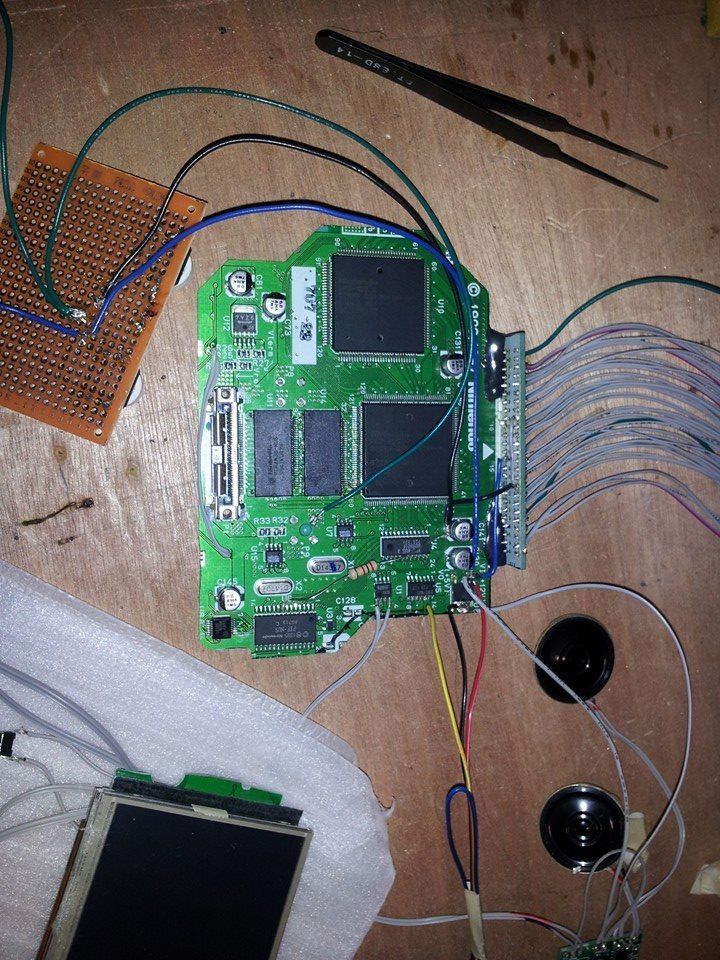
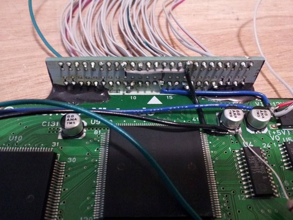
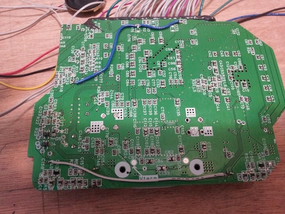
Here's some pics of the board with wiring. Maybe one of you peeps can see something wrong I can't...
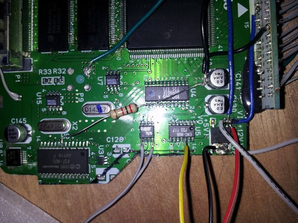
You can see where I tried the 2k resistor fix between pin 8 on the PIF and 3.3v in there too:
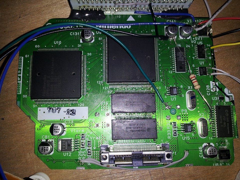
closer view of most of the wiring:
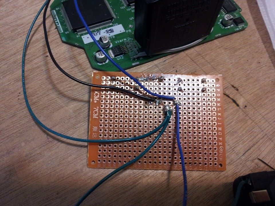
Voltage reg:
black wire = 3.3v output
Blue wire = 7.4v input
Green wire = ground
The screen which for some reason doesn't always show the 'AV1' in the corner but you can see flicker quickly when I switch on the power from the battery

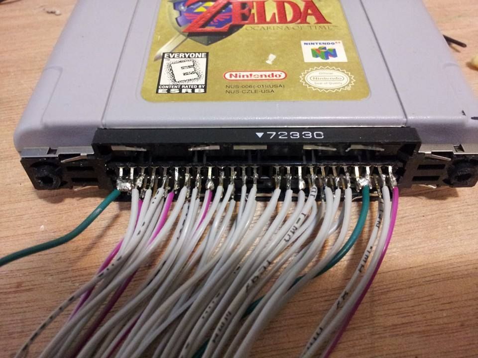
Jumper 12v/7.4v and 3.3v to the cart slot. based this off of daftmikes rcp pinout in the mega sticky:
which also allowed me to reduce the number of traces from the board to the cart slot by combining some of the grounds together on one thicker wire:
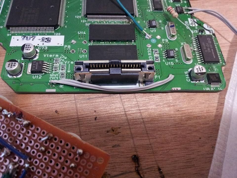
Front of the board where I cut close to the expansion pack slot and had to reconnect traces, front and back:
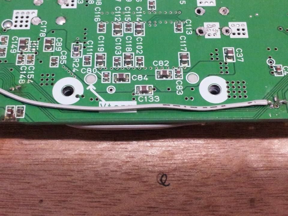
and the relocated 3.3v lines on the back of the board:
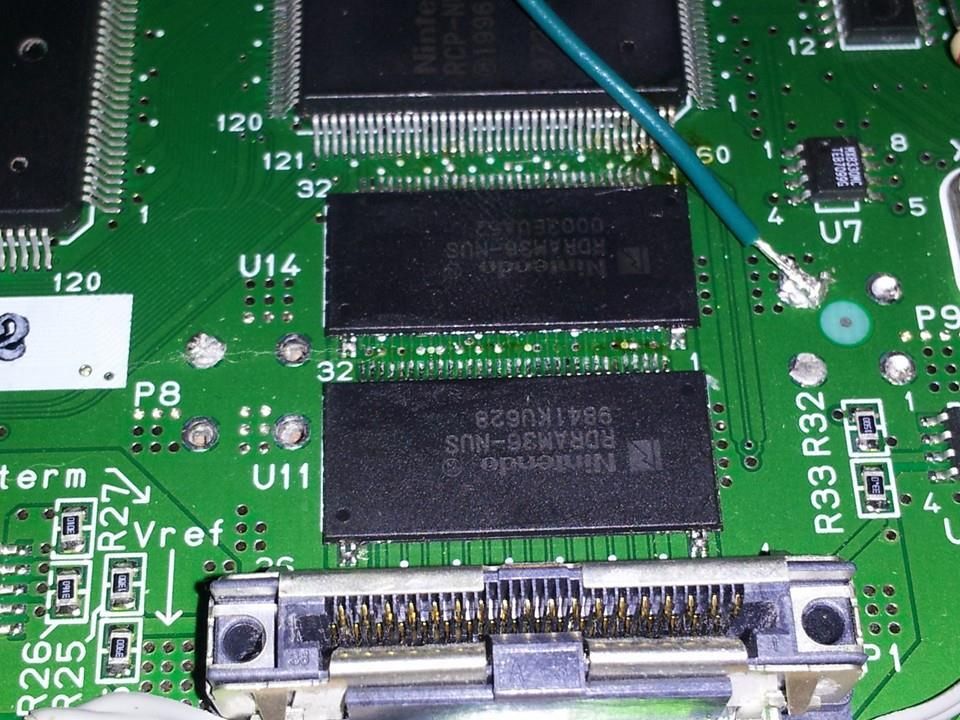
Pics of the new ram from the ram swap:
I have checked everything I can think of to see if something was grounded that shouldn't be, have 3.259v on my 3.3v lines, felt the chips while it was powered up and didn't notice any large amount of heat coming from any of them.
I did preform a RAM swap which I guess would not allow it to work which is kind of the only thing I can really think of right now as to why it isn't...
Opinions?
Comments?
Feedback is much appreciated lol
You can see where I tried the 2k resistor fix between pin 8 on the PIF and 3.3v in there too:


closer view of most of the wiring:

Voltage reg:
black wire = 3.3v output
Blue wire = 7.4v input
Green wire = ground

The screen which for some reason doesn't always show the 'AV1' in the corner but you can see flicker quickly when I switch on the power from the battery

Jumper 12v/7.4v and 3.3v to the cart slot. based this off of daftmikes rcp pinout in the mega sticky:

which also allowed me to reduce the number of traces from the board to the cart slot by combining some of the grounds together on one thicker wire:

Front of the board where I cut close to the expansion pack slot and had to reconnect traces, front and back:


and the relocated 3.3v lines on the back of the board:

Pics of the new ram from the ram swap:

I have checked everything I can think of to see if something was grounded that shouldn't be, have 3.259v on my 3.3v lines, felt the chips while it was powered up and didn't notice any large amount of heat coming from any of them.
I did preform a RAM swap which I guess would not allow it to work which is kind of the only thing I can really think of right now as to why it isn't...
Opinions?
Comments?
Feedback is much appreciated lol
