GBC overclock trouble

Hello,

Getting pretty desperate as i can't seem to get this simple mod to work. I have followed the original tutorial on this forum, and have read through all the pages without any luck.

This is what i have done
d75602a9-0870-4213-bd37-9992e87371a3_zps17dc7283.jpg


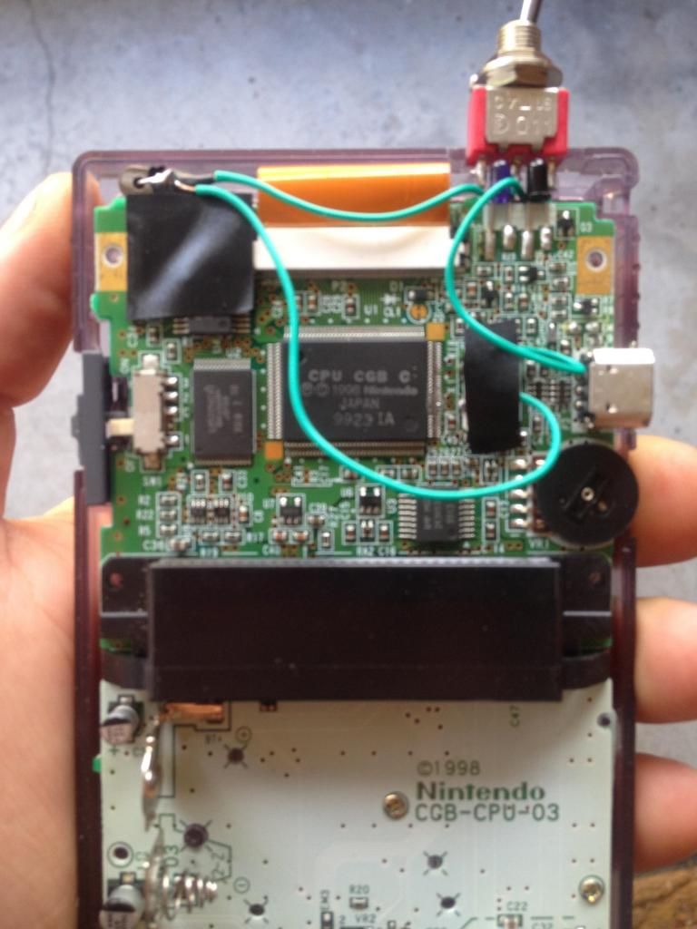
Using a 16mhz crystal with a three way switch. Soldered to the original crystal, but i havent removed the black ceramic top like suggested in the instructable tutorial. Do i need to do this?

I've reflowed all my joints with no luck. Hopefully someone can help. Is there a test i can perform with a multimeter to check?

Thanks
 
I've checked the switch with a multimeter, so that works. I've obviously done something wrong where. Is there a way to test for continuity through the circuit whilst its running?
 
Does it just run normally with the switch in either position? Have you tried starting it with the switch both on and off? Is the case of the crystal shorted to the leads coming out of it?
 
Have you tried anything else?

When I overclocked my GBC, I just removed the old crystal and used a 14.7MHz instead. I mainly played Pokemon on it, so there wasn't really a need for regular speed (I can't stand regular speed Pokemon now, way too slow).
 
I think the guide I was using said to rip it off with pliers. Mine ended up getting crushed instead of coming off in one piece, but I managed to get it all off.
 
If you are referring to the black ceramic half, that is just a cover isnt it? Did you use a switch? Either way would you have a picture? What you just said actually gives me hope. What i did is solder to the side of it rather than remove the black top (as per the instructions on this forum). The instructions on the instructables website are different and illustrate the same method you have used. Problem is i cant get a response from anyone that has left the black top intact.

Thanks
 
Re: Re: GBC overclock trouble

mrwonderful said:
Im never going to get to the bottom of this, am i? :(

I had the same problem. I had to remove the original crystal completely (well it broke when I removed the black ceramic top :p) to get the crystals I added to be recognized. The guide that is floating around does not mention this, so idk if its just different revisions or that was just implied.
 
Oh thank you so much. It's a miracle!

So if i remove the crystal, wont it only clock one speed? Is the crystal the black top part?
 
The crystal is inside it, and it's pretty small and as thin as a sheet of paper. If you can somehow break off the top cap of the gbc's resistor without damaging the crystal inside (possible but not likely) you can just lift one side of the crystal and solder that side to the switch. It's probably easier to just add another new crystal though, when I did mine I used a 4mhz and a 16mhz to under- and over-clock respectively. If you remove the IR port there's almost enough space for 3 new crystals for under-, normal-, and over-clocking put I can't find a switch suitable enough to toggle between all three, let alone one that would manage to fit inside the side the case.
 
You have confirmed my suspicion. I removed one on another board and couldn't understand why the black ceramic top piece had metal tangs? So it is just a tiny crystal within the ceramic?

So essentially the clock wont work unless the factory crystal is removed, or at least disconnected from one of its two contacts? Why doesn't anyone mention this? So if i want to have a normal/fast clock selection can i use the factory crystal (or one with the same spec) and use the toggles extra switch point? How would that work into the schematic?

Thanks for you help!
 
"Now solder a wire from one spot on the original crystal to the first point on the switch. Next solder a wire from th other spot on the original crystal and solder the other end to a lead on the new crystal. Lastly, solder another wire from the other lead of the new crystal to the second point on the switch. That's it. The picture following shows a good place for the new crystal."

Mentioned nothing about removing the original.
 
So i managed to get the ceramic top off quite easily. Became very clear to me how it works. The crystal was in tact. I ended up tearing it when i tried to re solder a wire. So now it works, great!! Though i cant switch between clocks. If add another crystal for normal speed, how do i wire that in?

Is the factory crystal just some sort of a resistor. How is it so thin?
 
Here's how I did mine. One crystal is in the upper left, the IR Port LEDs are removed to fit in the other crystal, and a small notch was cut out of the corner of the motherboard to fit in the switch.

I used a 16mhz to overclock and a 4mhz to underclock; if you want keep "normal" gbc speed substitute in an 8mhz crystal instead. I find their really isn't a point to having an over/under clocked gbc with no regular speed anyway, as anything you would need an underclocked speed for (tetris for example) it's way too difficult to get there on overclocked speed, and too tedious to play the whole time on underclocked speed.

gbc1.jpg


The wires seem to rats nest a bit in that shot so here's a quick mspainted guide that hopefully makes sense as well.

gbc2.jpg
 
Back
Top