Gamecube Portable Audio Help!

Can someone please tell me/ show me how to solder speakers to the GameCube. I have and LCD screen that has volume buttons on it and i have a speaker, but i don't know where to solder the speakers so the sound will come from the GameCube to the speaker yet i can adjust the volume using the buttons coming from the screen motherboard. I am also wanting to connect and audio jack for headphones but i don't know how to do that either.

here is the screen i have : http://www.ebay.com/itm/VGA-AV-driver-b ... 5902wt_904

And here is my speaker : http://uedata.amazon.com/Dynex-DX-PS1-B ... B005Y1COPY

please help it is the last thing i need to do to finish my GameCube portable.
 
You'll have to post actual pics of the devices as you have them now, not the stock photos, to really be of any help. We have no idea what those look like on the inside or what the terminals look like close up. Those + and - on the LCD controller look, imo, to be screen menu control buttons, not volume control, though i've never used those screens before, they are similar to car backup screens.

There are other topics/worklogs on here that show how to hook up headphone jacks if you do a little digging...

viewtopic.php?f=36&t=13773

naimlessone said:
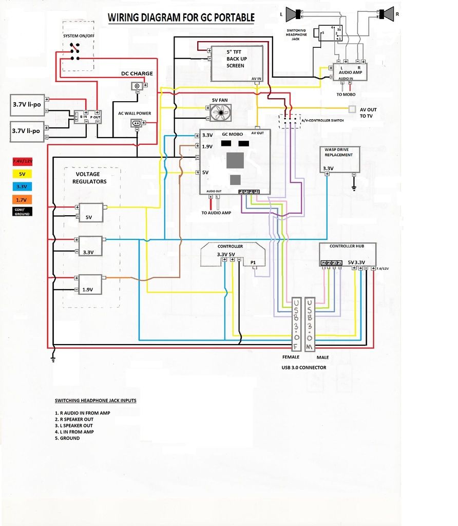
I know this is kind of small to see, not sure how to get it bigger, but if you ctrl-+ a few times it's easier to read. I started drawing this the other day in pencil with a straight edge. Went back in with paint to make it clearer what had to go where.

Still missing a few little things, like the connections to the Wasp, but other than that, I believe this should work.
WARNING! I am not 100% sure that this diagram is correct. To the best of my knowledge it is, but this being my first GCp, this is a work in progress.

EDIT: fixed, cleaned up and added some points in the diagram, with switching headphone jack wiring points. Obviously the WASP gets either wired to an ffc cable to the board or MEGAdrive adapter so I didn't show that because there are multiple ways to do that. And just a note, you do not need to take 7.4-14.8 volts to the controller hub at all. I am doing this as I intend to put put LEDs inside of it as the case I'm using for the controller hub is a clear case as I've shown in previous posts.
GC%20wiring%20diagram%201_1.jpg


I hope that this diagram helps clear up some stuff that I've seen multiple people post questions about. I will be following this verbatim unless I find something that I did wrong, in which I will be sure to fix the picture to show.


This is more help than you should need. If you can't finger it out with that pic....
 
I have the exact same driverboard for my LCD AT050TN22.
The audio amp on that board has been removed completely so Audio won't work thru the board I'm afraid.
There was a guy here who was looking to make it work but after contacting the supplier who only spoke Chinese and as much English a seller from alibaba can speak he got nowhere. Try contacting your supplier, maybe he knows more. But I doubt it.
 
thank you for the info so far... i will post pics of the GameCube tomorrow... it is at another location so i can't now but again thank you for the info so far. it helps.
 
Back
Top