Downing
Well-Known Member
Hey guys!
I know I've been quiet for quite some time but I've be buried in real life and case commissions as well as my own projects that finding the time to actually post has been difficult! But enough of that. I've got a few projects going on now that I've been slowly making progress on, but one of these projects has required me to do a lot of SMT component soldering.
To those who don't know, SMT stands for "Surface Mount" components and can get super small and require a whole new look upon soldering in general. This in turn has led me to think that if the progress of my project continue, I'll need to have some form of SMT support.
I saw this last year on Hack-A-Day and was quite impressed with its simplicity and accuracy. Though I had no use for one at the time it kind of got filed away and forgotten. But, then came this project and it really made me realize how important a steady hand is, which I'm finding I'm not as much as needed.
So this little aide, should I get it working correctly, will really allow me to take the headaches of using tweezers and hope to a more stable level without breaking the bank. He says this can be made up for less than $100. We'll see if he's right, but for now here's what I have drawn up.
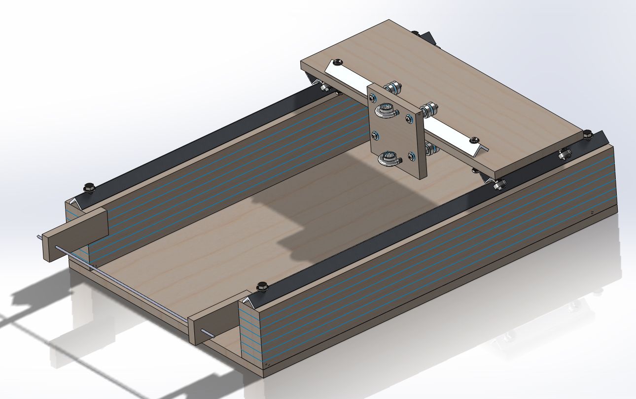
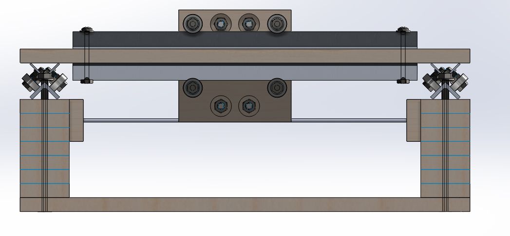
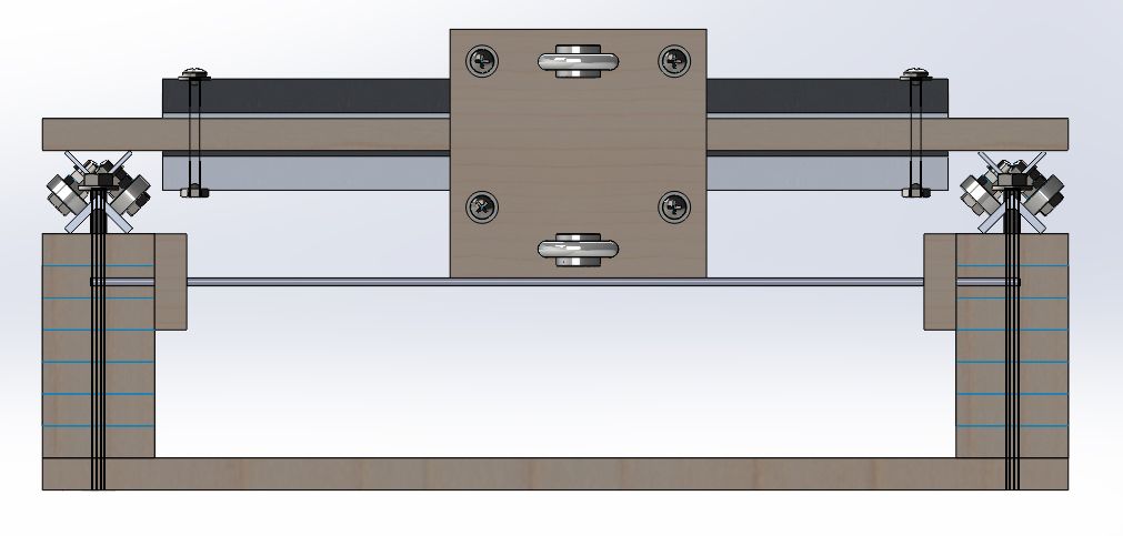
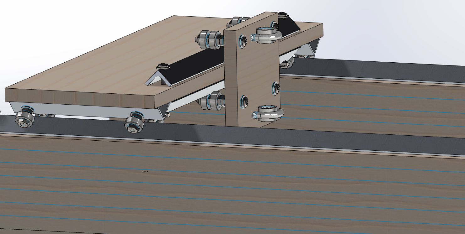
All in all I'm liking how this looks in 3D and hope I can make it translate into real life. We'll see soon enough I'm sure and I'll have more updates on the project that's been taking up all my free time in the next few weeks.
I know I've been quiet for quite some time but I've be buried in real life and case commissions as well as my own projects that finding the time to actually post has been difficult! But enough of that. I've got a few projects going on now that I've been slowly making progress on, but one of these projects has required me to do a lot of SMT component soldering.
To those who don't know, SMT stands for "Surface Mount" components and can get super small and require a whole new look upon soldering in general. This in turn has led me to think that if the progress of my project continue, I'll need to have some form of SMT support.
I saw this last year on Hack-A-Day and was quite impressed with its simplicity and accuracy. Though I had no use for one at the time it kind of got filed away and forgotten. But, then came this project and it really made me realize how important a steady hand is, which I'm finding I'm not as much as needed.
So this little aide, should I get it working correctly, will really allow me to take the headaches of using tweezers and hope to a more stable level without breaking the bank. He says this can be made up for less than $100. We'll see if he's right, but for now here's what I have drawn up.


All in all I'm liking how this looks in 3D and hope I can make it translate into real life. We'll see soon enough I'm sure and I'll have more updates on the project that's been taking up all my free time in the next few weeks.