Composite a/v out for Intec Wii screen

Xerox

Member
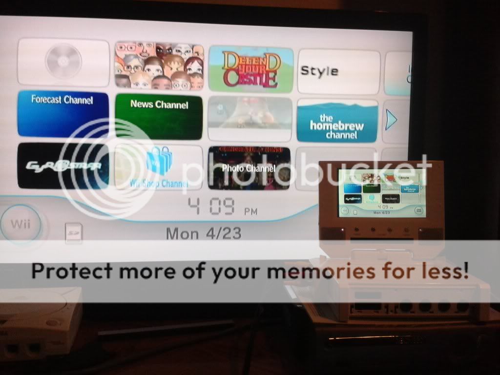
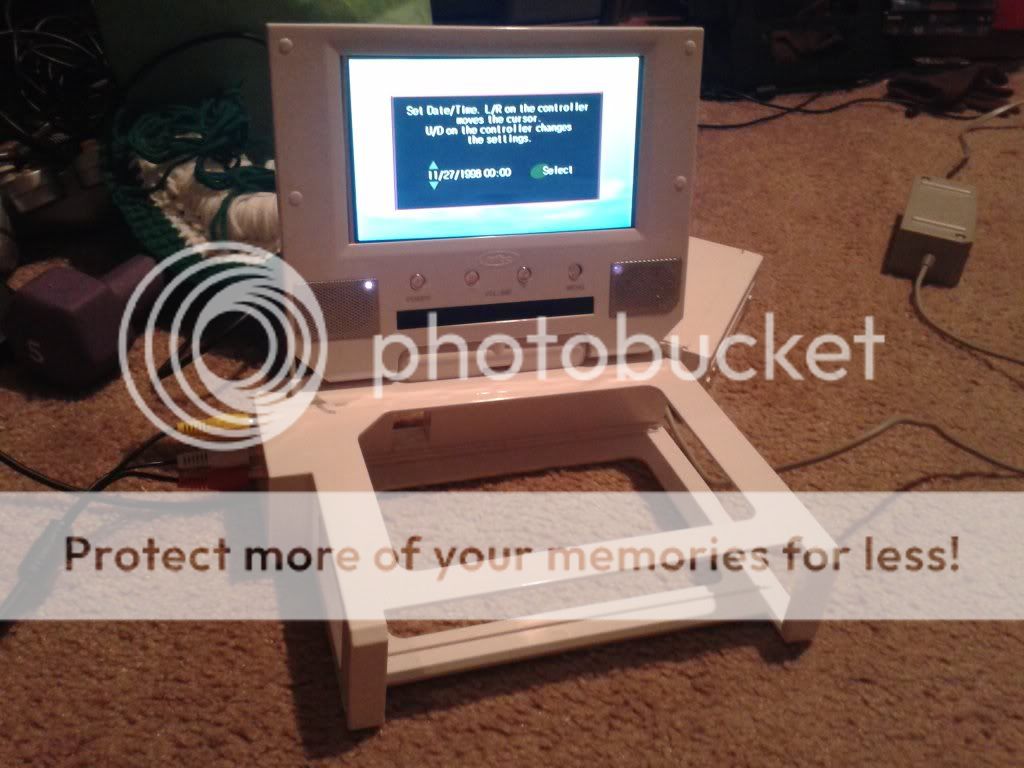
I bought a 7" intec wii screen to help me out on "making" a simple first portable. However, I'd like to add a/v out to still be able to plug it into a TV in case there's a nice big one nearby.
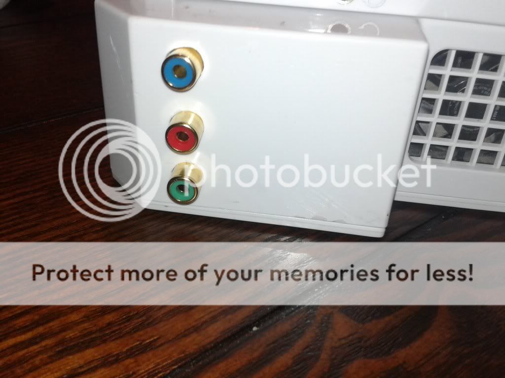
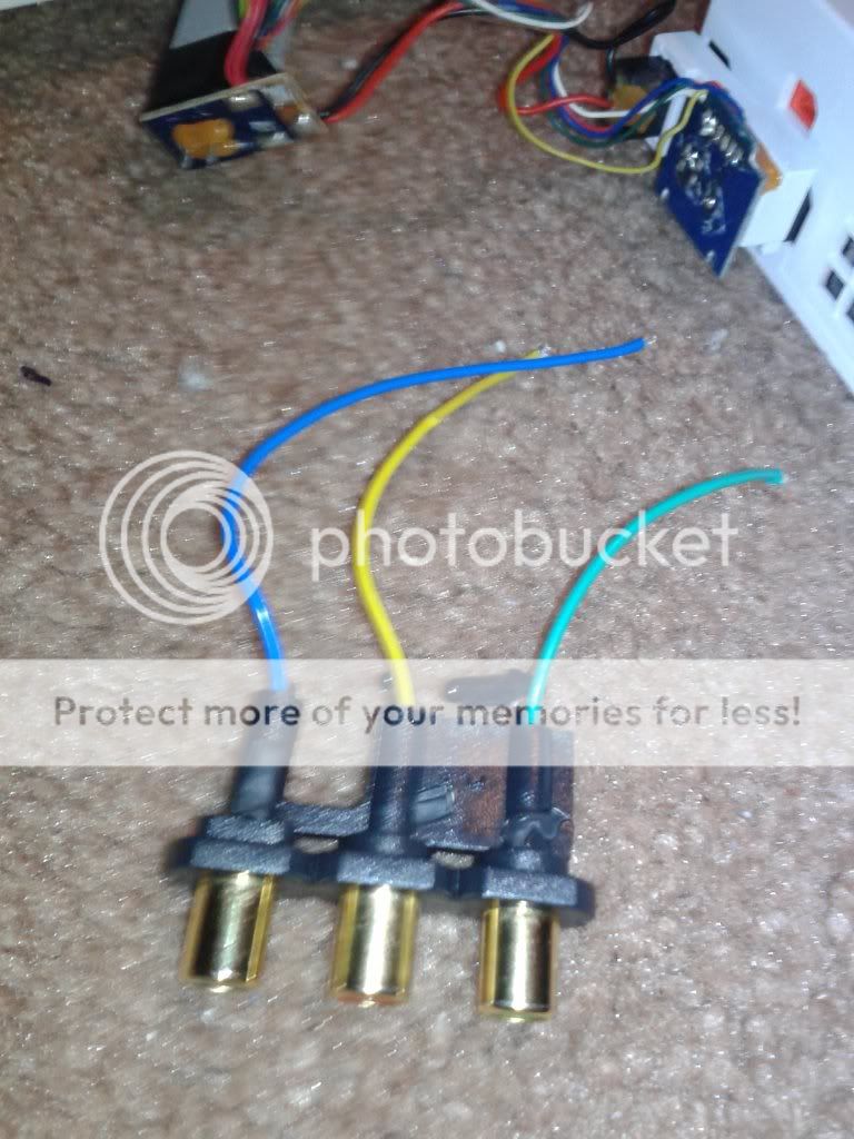
Well, I looked around the apartment and found this original Xbox high def converter and gutted it for the female connectors. (Pics to follow) I then opened up the screen housing to attempt to wire them up, but for the life of me I can't figure out how to go about it. (I'm a bit new to this sort of thing)
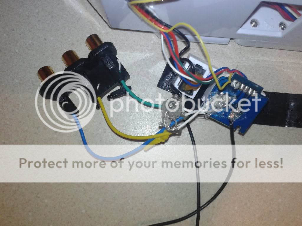
I see this circuit board attached to the wii a/v out and figure that soldering on the wires to my sockets at these solder points would make sense. But none of them give me audio or video. Am I doing something wrong? Might these not be solder points for what I need? I'm sure I could break things down further, but this seemed like the easiest place to try and connect them if possible. Thanks for any help at all!
IMG_20140208_173455_zpsbec67144.jpg

IMG_20140208_173310_zps15de5edb.jpg


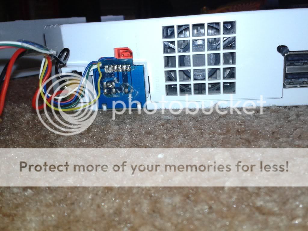
Just realized it may be hard to tell, but I'm speaking of the six solder points at the top of the blue board. The leftmost two make a buzz come out of the speakers on wire contact, and the rightmost two make the screen's video flicker. But neither cause any output when hooked up to another TV.
 
Just a bit of additional info that occurred to me:
Are component cables special in composition in any way? I'm wondering if the ports from the Xbox converter just aren't capable of carrying the signal, though that doesn't make much sense to me.
Also of note, they've got a bunch of single copper wires inside, but also an odd white rubber insulated wire within the rest of the cord. I'll try to get a photo up of that as well. Why would there be a separately insulated part of wire within the cord itself?
 
Component cables are just straight RCA connections, nothing different from composite video. Are you sure that the Intec screen draws composite video from the Wii? I don't know anything about that screen but it's not impossible that it uses component, which would be why you don't get a composite video signal. If you first connected audio lines to some voltage source on one of those solder points, you could have damaged a capacitor or other filtering component in the speakers. That would prevent audio from actually getting through when you connect the right points. It's also a possibility that there are just other connections on the other side of that board that aren't necessarily accessible or visible from the back.
 
Well, checking some of the 64 threads tipped me off to something I didn't realize. The inner cord for my female connectors is the lead and the shielding around it needed to be grounded. After some fiddling, I found the bottom rightmost solder point was the ground! I grounded all my connectors to the same wire, then hooked them up to the corresponding points. The leftmost two on the bottom were audio and the one to the right of them was video. (I also found video and ground hidden in the six top solder points, at points 5 and 3 respectively)

I wanted to quit after just connecting the video, since I suck at soldering and figured I could just send the audio out through the headphone jacks. But fear not, I persevered and prevailed.
IMG_20140210_225149_zpsabdbab58.jpg

Added some hot glue to hold it all in place. It doesn't look pretty, but it works. Now this baby can split output to a TV or accept input from anything else! Really pumped since this is the first I've done of something like this. It's very rewarding when it starts to come together. Now to drill some holes and mount these things.
 
Actually the outer drum form the female jacks ARE GROUND. I know this for a fact, I've been working on a RCA related project. If you don't ground them the image will stutter and may damage your TV.

Sent from my GT-I9500 using Tapatalk
 
Yep! That's exactly what my problem was; check the post immediately above yours. I grounded all of the 3 wires to the same point and it looks great.
 
Well, I didn't allow myself enough room between the board and the hot glued joins to screw everything back together, so I had to solder some longer wires in there so it would all fit and close up. Worked as more practice for soldering, which I needed! (Could probably use a better tip too)
So I drilled some holes and after some trial and error, everything works! I may paint the sockets the correct yellow/white/red colors, but for now it works.
IMG_20140218_070255_zps93c36145.jpg

IMG_20140218_070558_zps70e9b880.jpg

Input too! (As long as there's no wii in the case)
IMG_20140218_071037_zpsbd9be9dd.jpg

IMG_20140218_071047_zps1dd30074.jpg

I'm digging it. I was gonna make more modifications to this portable, but I think it works well to just slide my main wii into. I think I'll work on making a more handheld portable with my other wii. Ambitious as it may be for me, I've got time.
 
Back
Top