Kyosho
NOT KYO
I'm trying to get the analog triggers on an Xbox 360 controller to work like a normal button. Rather than the analog of somewhere in between. On episode one of the Benheck show (11 0ish), Ben shows you how to do it, assuming you kept the pots (and perhaps glued them in place so they don't rotate). However, I desoldered mine because there wasn't space for them. Well, I've moved houses since then and have no idea where they could be. However, I know there is a way to do it without the pots, I'm just not sure how.
I searched here (nothing) and BH (nothing) and finally on the ArcadeControls forum I found reference to it. I figured they'd be accustomed to using 360 controllers for MAME cabinets and I was right. But it appears they usually just ignore the triggers entirely. However, I did find one thread on the subject. Problem is, there are two solutions given, and I'm not sure which is right:
Can anyone here weigh in on this? I tried registering there, but they apparently like to approve new members manually and I haven't been approved to post there yet. I figure some one here has done something like this in the past. Perhaps with the Dreamcast, but every DC portable I found had the triggers intact.
I searched here (nothing) and BH (nothing) and finally on the ArcadeControls forum I found reference to it. I figured they'd be accustomed to using 360 controllers for MAME cabinets and I was right. But it appears they usually just ignore the triggers entirely. However, I did find one thread on the subject. Problem is, there are two solutions given, and I'm not sure which is right:
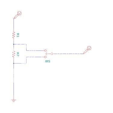
Franco B said:There are three pins on the pot/pad. If you look at the pad as if you are holding it, bridge the bottom two pins with a 10k resistor. Attach a ground wire to the bottom pin and attach the NO terminal of the buttons microswitch to the top pin.

r3ll1k said:One is to remove the potentiometer if you do the best thing to do is solder 2 10K resistors to the contacts so that they won't register as open. You then solder a wire to the middle contact as your signal wire and then wire the ground wire to any common ground on the controller.

Can anyone here weigh in on this? I tried registering there, but they apparently like to approve new members manually and I haven't been approved to post there yet. I figure some one here has done something like this in the past. Perhaps with the Dreamcast, but every DC portable I found had the triggers intact.