REV C - MoBo - Where are the following ports

KazuyaX93

Member
Hey Guys,

I got a PAL (REV C) Gamecube and I don't know where are the following ports: "3.3V", "1.9V", "12V".
I want to build a GCp, but this tutorial is not REV C - Friendly :/
And I need the Information to wire my WKF to the Gamecube.

wp_0003201zhb3s.jpg
 
SNEAKxxATTACK said:
If you really think the pinout is incompatible, use a multimeter and measure the output of every pin.

I can get a Multimedia tomorrow, but it would be great if anyone could tell me the locations of the ports.
 
Front:
wp_000321e4q74.jpg


Back:
wp_0003221pxq1h.jpg


Could be a NTSC-MoBo D: I got the Gamecube from a german friend.
Do you know where I can find the ports that I need to wire my WKF to it?
 
I can use these Pinouts for my WKF, right?
Could I wire near the blue transistors, right?

revc3.jpg


I'll buy a Multimeter tomorrow :)
 
To power your wii key, 3.3v

and for pin 29 NO switch needs 1.9v

Gooza and ashen both made guides on wiikey wiring for gamecube
 
SNEAKxxATTACK said:
To power your wii key, 3.3v

and for pin 29 NO switch needs 1.9v

Gooza and ashen both made guides on wiikey wiring for gamecube

Thank you :)

I use the Tutorial from Gooza, but he used a Rev A/B MoBo, so I asked for the pinouts for the REV C MoBo :).
 
does rev C not have the same dvd port as rev A/B?

I'm pretty sure they are. I have both boards in front of me. And I never read anywhere that they are different (in dvd connection at least)

So wire the wiikey by gooza's guide
 
SNEAKxxATTACK said:
does rev C not have the same dvd port as rev A/B?

I'm pretty sure they are. I have both boards in front of me. And I never read anywhere that they are different (in dvd connection at least)

So wire the wiikey by gooza's guide

Pin 32: This pin on the WKF needs 3.3V to power the chip.
- You can connect with a wire from the breakout board / ribbon straight to 3.3V on the gamecube mobo.
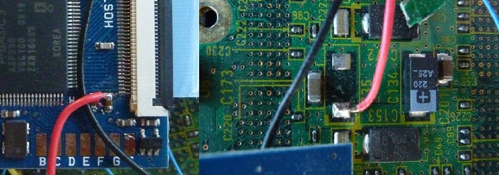
- Alternatively, you can also connect a wire between one of the capacitors beside pin 32 and the gamecube 3.3V, as seen here:
pin32.jpg

On the left is the connection to the cap next to pin 32. The right shows one of the points on the bottom of the mobo you can use for 3.3V (test with a multimeter if you have one to be sure you’re using the correct voltage).

The position of the 3.3v Pinout is on a another position.
 
The confusion would be all cleared up if you had a multimeter. Which you are getting today anyway right? Kinda figured by the time change between posts and the current time in Germany. Then measure the voltages in the dvd pins, and if the voltages match up, most likely the pinout in the guide will be correct for you as well.

Anyway the change in position is to bypass some pins and power directly to what needs certain voltages. The 3.3v is going to the wkf, and is being tapped from the spot according to the picture. but you want to tap from a different place according to the picture from hailrazer's guide.

^--(Get voltages from where you can get it)--^
 
Back
Top