Miceeno's Nintendo Sixty 4or the Win

Miceeno

Member
I've been working on a portable N64 for a while now and I'd like to share it with the community. Usually I lose interest and abandon my projects but I figure if I start a thread for it the chances of that will be a lot less.

Here are some pictures of the case work I've done so far. I'm frankencasing an old Netgear wireless router. The camera on my S3 sucks and refuses to focus properly but you get the idea.

1wa0.jpg


As you can see I've used the D-pad, XYAB pad, and the speaker grill from a DS Lite. The rest of the buttons are from a PSP 2000. I have analogue sticks from the PSP and 3DS but I'm unsure as to which one to use. I'll probably use the PSP stick because word on the internet is there's more travel on the 3DS stick and I've used the hole from a PSP. I have some good trim pots and will be using a 3rd party N64 controller so it should work out either way.

wcne.jpg


The top of the case has the RLZ and screen control buttons.

9xs0.jpg


Speaking of the R and Z buttons the ones from the PSP weren't tall enough and because of the shape of the acrylic sides I couldn't mill a pocket. So this was my solution.

v1pn.jpg


The bottom. From left to right: DC in, charge LED, volume, power switch, reset button. I'm including an internal smart charger so there's less switches and power in but I still feel like I'm missing something.

ipys.jpg


fm8d.jpg


1i69.jpg


sb5w.jpg


The back.

ToDo:

Paint.
Build the RZ squishy tact mounts.
Trim the N64 via Bud's guide with a 180 deg Ashen fold.
Assemble.

Simple enough.

Does anyone know the best paint to use? I've abandoned previous portables because of Krylon Fusion and it's screwy goodness. That crap always seems to crackle or go on so thick it clogs my ventilation holes. I'm considering trying Rustoleum's American Accent line even though Rustoleum isn't the goto for plastic. Primer should make it stick to plastic, right?
 
Krylon Fusion is what I would use, I think it becomes part of the plastic because it chemically reacts with it or something. Just apply a light coat to it should solve any problems you have with it :)
 
Painted. I made a slight mistake and painted one of the wrong PSP buttons. The square one isn't square (get it?), it has a taper to it because the PSP tapers away. So one of my buttons has an angle to it. I'm probably going to paint the other one and replace it, but the taper will give the Start button a more ergonomic feel. Oh and the buttons only look sunken in because they being held in place by scotch tape, they will stick out when the squishy tacts are behind them.

EDIT: I mean the circle button has the taper. Shows you how familiar I am with Sony's consoles.

525j.jpg


mbvi.jpg


xkx3.jpg


lhuf.jpg


Does anyone know of a good place online that will print high quality vinyl stickers? I'd like to put this logo somewhere on this portable. The color scheme will match of course.

uixv.jpg


And now the real fun begins!
 
Great looking case, I am really liking the way it looks. As for the vinyl skins, I use a site called gelaskins.com when I want skins for my phone. But they have other things that you can cover too.

So I dont know what size you want yours to be, but maybe you can just pick one that is a box shape design and then you would be able to cut it out and stick it on your case.
 
I looked at the site and $15 is pretty affordable for a phone sized sticker. I'm going to have to start working on my image(s).

More progress. I finished the shoulder buttons. In previous abandoned projects this was always the most dreaded part but this go around wasn't too bad. I got lucky and found that the screw posts inside the case could be double purposed.

s48n.jpg


wsdn.jpg


4sez.jpg


I went with the Rustoleum over the Krylon Fusion and I'm pretty pleased with the results. Upon closer inspection you can see black specks on the white and white specks on the black. It's really not bad enough to repaint but I learned my lesson about over spray and painting two colors too close. It's also a bummer that the only primer I could find was black which makes the scratches/chips stand out.
 
More progress! I've finished the bulk of the buttons, it was a lot less difficult than I originally thought it would be. Here's some pictures.

7ix7.jpg


2y80.jpg


05qu.jpg


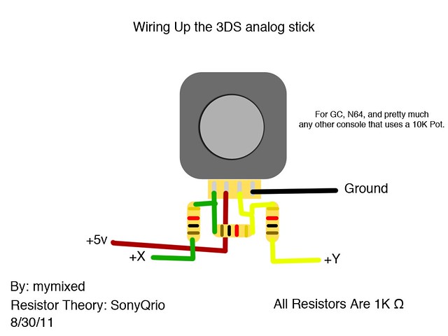
Ok, so before I can put the batteries in I need to get the PSP analog stick figured out. Please don't flame me for not using the search, because I have, but I can't find the topic that had good info on PSP and 3DS sticks. I used the have the link in my email but I can't find it either. It could possibly be on a different forum but I'm sure it was on this one. In my searches I've discovered that there are many types of PSP sticks floating around. Here is a picture of mine:

wokt.jpg


bsce.jpg


I also have a handful of these: http://www.ebay.com/itm/250878854331?ssPageName=STRK:MEWAX:IT&_trksid=p3984.m1423.l2649

I'm kinda unsure on not only the pinout of this stick, but the orientation as well. I will begin testing as soon as I tear into my 3rd party N64 controller.

Looking at the bottom picture, would it be safe to assume the following pinout?

1) Y
2) V+
3) X
4) GND

What voltage do these generally take? Do you guys think I have the V+ and the GND backwards?
 
In order to get the PSP stick to not interfere with my battery placement I've gone ahead and trimmed the board. After some dremel fun I got the new location of the wires to agree with the rest of the stick unit. I've also folded the wires to conserve space but it makes it a little difficult to see my work.

0oly.jpg


Here's a crappy unfocused picture of the pots and the controller. Does anyone know what it takes to get a half decent picture from a Samsung Galaxy S3? My previous phone, the iPhone 4s seemed to be able to take decent pictures most of the time. (Switched to android because the emulators are better and my general hatred towards Apple, lol. The only reason why I ended up with an iPhone in the first place was for App Development for my job. Not that people really care about such things on this forum.)

tz6t.jpg


I've also found the threads that I was looking for:

http://forums.modretro.com/viewtopic.php?f=33&t=8256&p=108358
http://forums.modretro.com/viewtopic.php?f=36&t=8250

I think I might have to order another 3ds stick as I can't seem to find the one I ordered months ago. The people in the threads above seem to have had better luck with the 3ds stick. I tried some of the same things they had going on with my stick but I'm not really getting anywhere.

I have found that swapping the ground and voltage swap the axis that is inverted. Good to know. Although no matter what I've tried one axis is always inverted. I tried, as MyMixed and SonyQrio suggested, to put resistance between the X and Y to uninvert the axis but it seems to only decrease the range on the stick. It also seems like range on the left to right are equal but the up is only about half of what the down is, regardless of the ground and voltage orientation. Does this mean that these sticks are worthless?

I think I've come across people programming/selling micro controllers to solve these problems in other forums/topics. I think I will dig around and try to find the person who sold them. I'm pretty sure Shock Slayer used one in his TSFv2 and he might have had Ashen program it for him.
 
I know this may not be the best suggestion, since it's clearly for a 3DS slider, and I have no experience wiring PSP sliders, but I don't see why it couldn't work with some adjustments. Same kind of joystick, right?

And, about the rest of the portable... WOW. I just dream of making something look so clean, but I guess I lack a lot of tools (I freehand so many things). It makes me so envious. Everything looks amazing.
 
Thanks for the compliment!

Most of this is free handed, the shapes for the buttons from other cases would be miserable to do on a mill. I have a 3ds slider in the mail and hope it arrives before mid October. I didn't think buying a circle pad pro was worth the money so I ordered one from China. I also ordered a generic analog slider which looks like a PSP analog but I think its specific for project use (non replacement part), so it should function more like a standard 10k pot analog.
 
I'm still waiting on my 3ds stick in the mail. I got the generic project stick but it was identical to the PSP stick which doesn't work. I've made a little bit more progress. I've add speakers and the amp. Although the amp is broken, in fact both of the amps I order only have one working channel. I've considered using both to get both channels but I've ordered another amp to try first. All the amps are based on the PAM8403 chip but the one I've ordered is a different style and supplier.

These amps are 3 watt per channel. I don't know what the wattage and impedance of the DS lite speakers but they are defiantly greater than this speaker: http://www.mouser.com/Search/Produc...-Rvirtualkey66500000virtualkey665-AS03508CO2R I started with this speaker but it sounded like it was going to blow at half volume. I know it's a 1W@8ohms, but I figured the amp was 3W@4ohms which would put out 1.5W@8ohms. I get a fuller range of volume with the DS speaker (not full but close).

Here's the amp that only has one working channel.

q8ty.jpg


9zdm.jpg


And in my portable (before I tested the second one).

7wzd.jpg


The new amp.

http://www.ebay.com/itm/Small-PAM84...t=US_Ham_Radio_Amplifiers&hash=item3cd15a1829

If the new amp doesn't work and I don't feel like messing around with frankensteining two of them together I may use a regular LM386 amp circuit. The upside to the LM386 circuit is that it can run on anything between 5V and 12V (I may be mistaken). Whereas the amps I've bought only run on 5V. I'm not sure if I want to steal the 5V off of the N64's regulator so I will have to add my own 5V source along with the 3.3V. If I add my own 5V source I could probably run both the amp and the N64 off of it. The N64 only uses the 5V line for the DAC which can't draw too much. And if I use a switching regulator for the 5V line I can run my batteries to a lower voltage because the crappy low voltage dropout regulator on the N64 doesn't run on anything below 6V (I think). I'm not sure how much lower 7.4V Li-on batteries can safely go but it may get me 20 minutes more play time.

I've also prepared my smart charger.
Before:

pyb9.jpg


qb8a.jpg


After:

u2pv.jpg
 
Small update here, no pictures though. I've been extremely busy with work lately and haven't had a chance to work on this project. Overtime FTW!

I've been waiting for a new audio amp from china which should have been here anytime between October 24 and November 7. Needless to say it never arrived. The seller on eBay assured me that they would send a second one out and that I should expect it soon. So in the mean time I figured I'd tinker with my broken amps. I discovered that one of the caps is missing (C5 in the above pictures) and that by replacing it the amp becomes fully functional.

I also received my 3DS analog stick and it works flawlessly with 3022 Ohms on the X, 3525 Ohms on the Y, and without the 1K Ohms bridging the two just as ShockSlayer stated.

The amp has been remounted and I've added the 3DS stick. I've also got the smart charger, the 3.3V regulator and the 5V regulator. The only things left to add to the front of the case are batteries, battery protection circuit, controller, possibly a memory pak, and the LED fuel gauge for the batteries. The next chance I get I will be trimming the controller board. From here on out the pictures will be much better as I've managed to get my hands on a Sony NEX 5.
 
It's been a while but I've made some progress on this. Originally I took a break from this because soldering to the traces on the controller pcb was impossible and I didn't want to murder more of them then I have to. I've massacred many N64's learning to relocate ram, trim the pcb, and bend the cartridge slot, etc. and I feel terrible (all that dead silicone on my hands). So when my victim controllers arrived I decided to put this project away for a while. Then life happened and I haven't been able to get back into this project.

xkj2.jpg


Now that I've decided to get back into this and to make my life easier I order some of those qfp breakout boards. Although come to find out there isn't a standard qfp chip under the black heat goop. I heated this up with a heat gun and come to find out its just a bare silicone die under there. So I'm back to soldering to the traces on the pcb.

In the picture the die is that square that's flipped over and to the bottom right of the place it was sitting in. It kinda fell apart with the heat.

abzaa.jpg


So here's the new controller pcb. I've already cut out all the parts associated with the memory/rumble pak slot. I don't plan to have that support in this portable, definitely on the next (bigger) one. I've also done a quick photoshop job color coding the traces.

822z.jpg


And finally here's the finished trimmed pcb. I've still got to relocated two caps and one resistor. Also, I've scratched the solder mask off where I've got to solder to the traces.

n7b8.jpg


bou8.jpg


If anyone can recommend a good iron for doing this please do so. I will probably buy a new iron seeing as my radio shack one I've had for years sucks. It eats tips like mad and is way to hot and large for this anyway.
 
So I tried again to solder to the pcb and after an hour of starting over I've given up on trying to make the controller pcb smaller.

cmfn.jpg


So instead I'm putting the controller where I was going to put the N64 and now I have an empty spot by the speaker.

lfruk.jpg


By doing this I've had to add a spacer to the back of the case.

dns0.jpg


With the added space I can build a better heat sink. Instead of using one piece of copper sheet sink I've soldered together a couple of pieces. I used plain old lead free solder (like the stuff you use when you normally solder, no braze or silver solder or whatever) and a heat gun. I hope it dissipates heat better otherwise I wasted copper and time.

s4us.jpg


g9eaz.jpg


p93h.jpg


The last image isn't accurate anymore because originally I was using a rev 6 board and it decided to die/sleep moments before relocating the cartridge slot. I'm now using a rev 4 board because it's what I had lying around. I hate to waste a rev 4 (or 3) board because they are good for ram swaps and RGB mods. Anyway with the two ram chips onboard I had to take off the spacer and put a wider one on.

Here's the rev 6 board. I've been using 3 pin fan plugs for the power and output so I can constantly test every step of the way. I hate when you put all this work into a board and have it die randomly and you have to troubleshoot everything. I'm actually planning on leaving the 3 pin fan plugs on so I can easily disassemble and work on this in the future.

si3i.jpg


eyid.jpg


Here's the rev 4 board with the cartridge slot relocated.

EDIT: In case this might be helpful to somebody. I had to add a 75ohm resistor to the composite video line to get the picture to clean up. I only had to do this on the rev 4 board.

5nuz.jpg


Now with the N64 in the case. The controller is wired up along with the reset button. I have a 64drive that I plan to use with this regularly (that why I need a reset button). Speaking of the 64drive, everyone reading this should support Marshall and buy one. Marshall is a great guy to work with! He's been willing to answer all my questions related and unrelated to the 64drive.

2grxj.jpg


This is the portable moments before I closed it up.

m98fo.jpg


Last minute I added a battery fuel gauge that you can see through the decorative holds around the edges of the case. I put it on the back so it's not annoying.

8kr92.jpg


Here's the back of the case without the cartridge cover in place. In the first picture I have a jumper pak in because my ram expansion pak wasn't behaving. And the last two is the ram expansion pak with original heat sink bent to fit and hot glued into place. I assume it wont get hot enough to melt the glue.

18qt.jpg


z8yk.jpg


a9wk.jpg


Here's the back cover *cough* hot glued *cough* *cough* into place. Look, it's ghetto but I can get it off easier than epoxy and I didn't engineer a way to use screws.

2c3l.jpg


I repainted the back cover because (1) it was scratched up and (2) I didn't think this had enough black on it since I added the spacer.

Here's the rest of the case.

sujq.jpg


kjsz.jpg


kjsz.jpg


5efy.jpg


Notice on the last picture that there's a gap in the case. Yeah, it's because with the spacer the original screws where too short. And the only screws I could find were kinda big diameter wise. I turned them until it seemed like it would break then I stopped.

And finally here's it playing Super Mario 64.

pfpaw.jpg


711nr.jpg


There's scratches on the front of the case, and it looks terrible but I'm too far along to repaint that piece.

Now the last thing I need to do before calling this finished is find a good 3DS stick cap and get some stickers made.
 
Here's the image for the sticker. Please don't steal and use. It looks kinda jagged, buts that's because its being resized for the forum.

mj4o.gif


Here's the image in the N64 color scheme. I will be using the black and white one, this is just for the lols.

pjvs.gif
 
Miceeno,

I was wondering if you could explain how you hooked up the slider to your super pad?

The superpad I have seems to be the same gray one you used which has the following wires going to the superpad analog pots:

VG1
VD1
VC1
VY1
VX1

I assume the VX1 and VY1 are your x and y-axis points, but the VD and VC points i'm unsure of where to connect and its hard to see how you wired yours up in your pics.

I'm using these pots http://www.allelectronics.com/make-a-st ... mer/1.html

the super pad controller and, of course, a 3ds slider.
 
Actually this is pinout:

VG1: ground from controller
VX1: x axis
VY1: y axis
VD1: voltage from controller
VC1: voltage too, actually you can just bridge them
 
Supersonic, you are the effin man!

I'm about to solder this up and take it for a test drive.

do I still need the 10k pots though or can I wire it with just the 1k resistors as in MyMixeds diagram?

6098551219_38fc5afa67_z.jpg
 
I recommend you stick to the trim pots because they will allow you to dial the analog stick in to perfection. Otherwise you will have limited range or deadzone crawling. Start your X axis at 3022 ohms and the Y axis at 3525 ohms and then trim from there. Also, the resistance between the two axi doesnt change anything (atleast in my experience).
 
Okay, so no resistors between anything and just trim pots between my controller board and analog points?

I may have to get a higher sensitivity pots for this as the ones I have are a one turn and vary grossly when the slightest turn is made on them. But I think I could get like a 5k pot which would give me what I need for resistance and more precise adjustments, no?
 
Back
Top