Gamecube Portable Power Wiring

Icelvlan

Member
Hello,

Just looking to get some help with GC portable power wiring. I know these boards work because they come from badassconsoles.

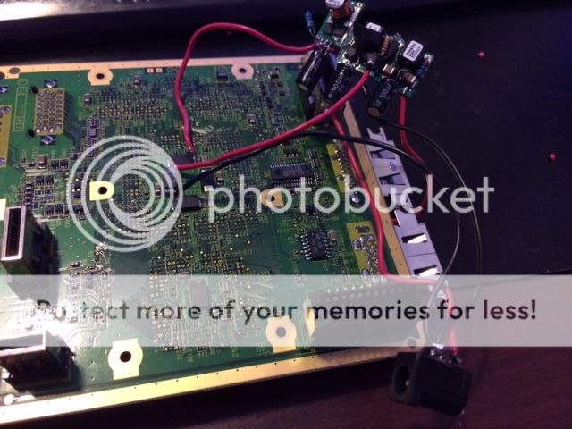
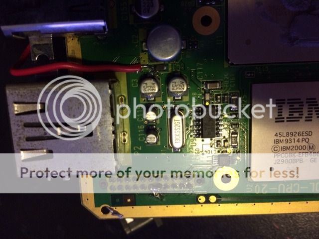
I've wired it using shockslayers TI regulator wiring diagram. 1.9v 3.3v 5v

I've also wired it as a trimmed board right to the components even though it's not trimmed yet using Ashens method. 1.9v 3.3v 5v and GND
I wired 1.9v to both spots as his diagram indicates. The power supply i'm using is a 7.4V 1.2A battery charger from battery space. Don't mind the 1.9V not being connected to the second point in the picture...these were the only pictures i had. But i did notice that when i connect both 1.9v points voltage drops to 0.7v instead of 1.9v from just one point connect. I'm assuming this might be because my PSU doesn't have enough amperage?

I'm using a multiout cable to get video on my TV and all i get is a garbled grey and black image that flashes on and off.

Looking to get a bid of assistance and can provide pictures if needed. I do have some experience making portables as i'm almost completed my n64p case painting left.


Thanks,

Ice
 
Oh sorry, I misread. Anyway you can't use a li-ion charger as a power supply, it doesn't provide constant 7.4v! Also 1.2A is not enough.
 
like other chargers it's rated at 8.4v though...i have a 8.4v 2.5a charger on it's way :)

what kind of amperage does the gc require to run?
 
Like Aurelio said, don't use a smart charger as a power source. It does more than just provide a constant voltage and it's meant to be connected only to batteries.
 
So this ended up being amperage...i fixed it by buying a 2.5A PSU.

Everything worked fine before my OMGWTF cut. I have a few boards to mess around with, so i wanted to try this one out first...I think the next one i might do the cut before this one.

Anyway, I did the the and am not getting any video on the screen. I feel the IBM chip getting hot...but not the other one. I checked my voltages and everything looked fine. I did sand the edges quite well after the cut as well. I reconnected the crystal and also the composite filter cap. I do see low voltages coming out of the composite cable, but no image. I read over the guide a few times, but feel like i am missing something. Something else i did was i left a bit of excess board. I don't know if this effects anything.

Here are pictures.


Have you checked every single edge for short circuits among the hidden layers? Since you cut the board, the GPU and CPU voltage lines are separated and it's possible that the CPU (smaller processor) has been bridged to ground. Sand all the edges carefully and check if it is indeed bridged to ground.
 
I can try sanding again in the morning. I used a rotating bit to sand. This is what I always used with my n65 cuts. What grit would you recommend? Also, is the crystal polarized does it have to be wired a certain way?

What's the best way to use my fluke to find a short? For some reason there is continuity to the 1.9v line to gnd even when it was functional this that tested the same which I found weird.
 
Icelvlan said:
I can try sanding again in the morning. I used a rotating bit to sand. This is what I always used with my n65 cuts. What grit would you recommend? Also, is the crystal polarized does it have to be wired a certain way?
I don't know about grit. I just use the finest sandpaper I have,

Icelvlan said:
What's the best way to use my fluke to find a short? For some reason there is continuity to the 1.9v line to gnd even when it was functional this that tested the same which I found weird.
There normally is about 30 ohms from 1.9v to ground because of certain capacitors. You should check to see if it is 0 ohms. That would confirm that there's a short; if not, there isn't one.
 
So it's 30 ohms right on. I tried sanding this thing down a few times, but still nothing. I did notice that both CPU and GPU and heating up now though.

Any other suggestions?
 
There is actually still continuity between bet the points in ashens guide....those diode looking things. I don't think a cable between both is required.

Correct me if I'm wrong
 
Just try it, if you have a rev A or B you need to connect both, connectivity just means there's connectivity. It may not necessarily be enough connectivity to carry the large current that the 1.9v line requires.
 
So I tried...resistance on one diode is one is lower on one than the other...also when connected together is 14...but still no go....sanded a bunch more as well. Should I be removing the component from the excess I left?
 
Back
Top