Yobo FC hacking Guide

Argelfraster

Well-Known Member
I was bored today so i made this guide:
REMEMBER THAT EVERYTHING GETS SOLDERED ON TO THE MOTHERBOARD.
These three board (by order) are
Power/AV board.........Mobo.............controller board
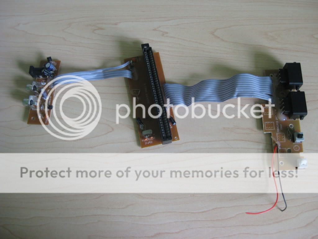
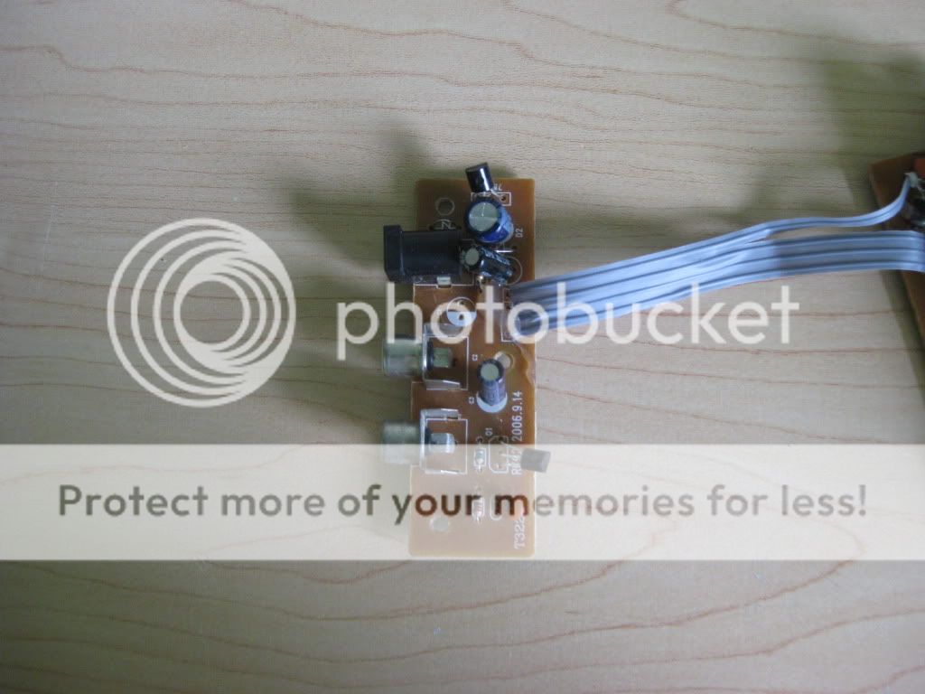
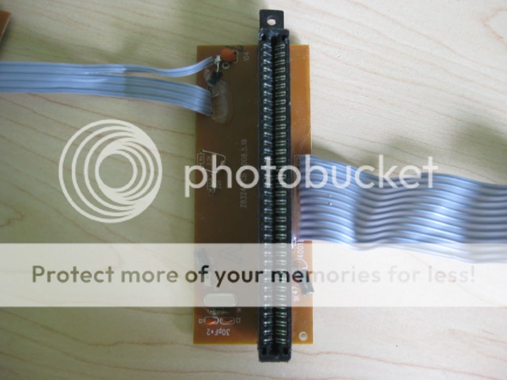
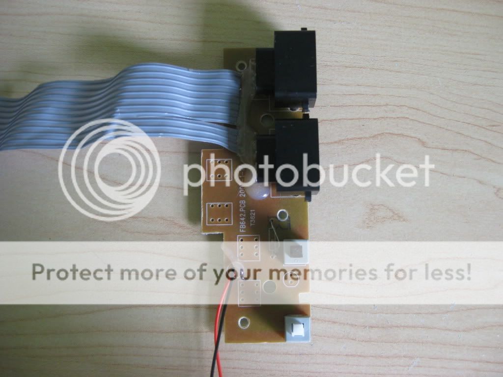
IMG_0171.jpg

Close ups of each:
IMG_0172.jpg

IMG_0173.jpg

IMG_0174-1.jpg

Now this guide is mostly written in the pictures, so if you don't understand PM me.
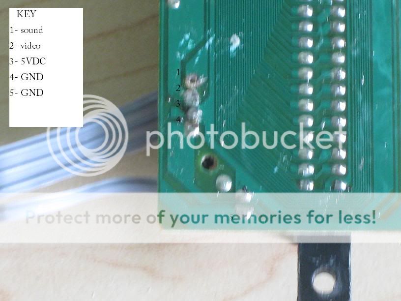
Power/AV to Mobo
IMG_0175.jpg

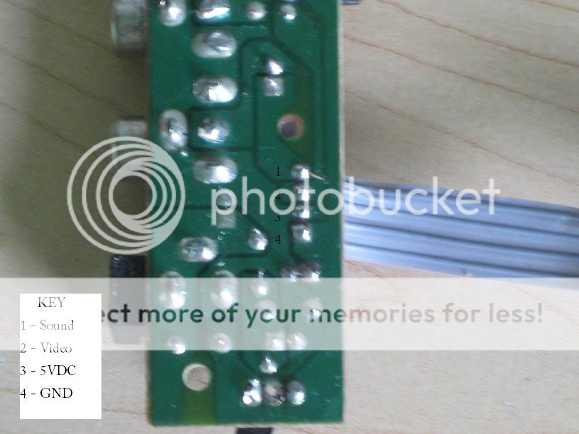
Its not a very good picture but you see 4 solder points, and thats all you need
IMG_0176.jpg

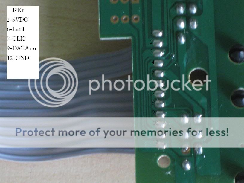
Controller board to Mobo ; THIS IS ONLY FOR CONTROLLER PORT 1!
IMG_0178.jpg

IMG_0177.jpg

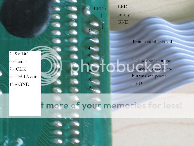
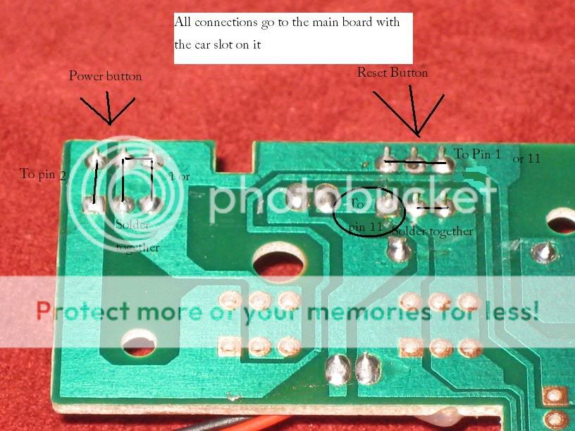
Power/reset buttons to mobo (where it says one or, it means to pins 1 or 11.
IMG_0179.jpg
 
I know this is a bump, but it is good info. My yobo came with a 6v dc wall wart, so it can definitely run on power over 5v.(I'm still using a 7805 on mines though). the a/v area can be removed, but what about the front board?
 
the front board acts as a 7805, right?
What? no.
There is no 7805, and if there were one, it would be on the back board.
Front board is just: controller ports, Power/ reset buttons and the power LED.
 
If they're NI-CD or NI-MH, you might be able to get away with using four cells, since it'll give 4.8v.
 
just CHECK your yobo, it clearly says 7805 on it.(although the 0 is a tiny bit scratched on mine, still visible as Heck)
 
I'm just using it for what will soon be a nes/snes metroid dubblesystem!(metroid and super metroid portable, with the carts hardwired in)
 
Sorry for the stupid question but the lines on the pic get solder together for the reset and power button and what do you do worth pin 1 and 11 first time doing this any help would be appreciated thanks again
 
Sorry to necro this thread, but it's one of the first links I found when attempting to repair the power regulator on my Yobo FC, and I'd like to add to the knowledge base here.

I received a free Yobo FC some years ago (no controllers or cables or anything included - I acquired these later) and purchased a cheap copy of Pinball to test it out. What happened was the power would momentarily come on - anywhere from a split second to a few seconds - then power off again. Subsequent attempts would always show the power coming on for a blink, then that was it. I finally got around to taking this unit apart, and my son saw the cheapy generic transistor used as a power regulator seemed to have partially crumbled. Attempting to move this transistor resulted in the black cap completely crumbling apart. This transistor was located in the portion of the power board marked '7805' with three circuit board through holes, and some research found that this system should be using a 7805 power regulator. My dad traced the line-outs on the board from the barrel connector, and was pretty confident that the pinouts on the 7805 would work (despite the old power regulator having its middle pin bridged outside the 7805 space).

Took a trip to RadioShack and acquired a 7805 (plus an extra, if something went wrong). Desoldered and removed the old broken transistor, then soldered in the 7805 (matching the pinouts to the board traces from the power connector). Plugged everything in and it worked! Power light came on, stayed on, and the game could be played. I had read something about the possible need for a heatsink, so my dad dug out a metal corner bracket that we affixed to the hole on the top of the 7805 with a screw and nut. It's not totally ideal - it should use thermal paste and the 'heatsink' should be made out of aluminum for best heat transfer, but we figured it would work well enough as is.

I've attached photos.


Just out of curiosity, has anybody figured out the current draw / wattage on this? Not the rated wattage, but the actual one. I can't imagine it's much, but I'm just curious what kind of battery power you'd need.
 
Back
Top