Hi there!
Recently, I've become the owner of a used Wii without power supply and cables. Infrared sensor bar is being replaced by candles (works great! ) until the package from China arrives. Power comes from an old PC PSU 12 V line.
Right now, I am trying to connect my Wii mainboard to my TV without an original Nintendo a/v cable, but with wires, soldered to the connector pins. Using Google image search, apparently, there are various cables existing:
For the current state of my project, I'd only need composite video, no RGB, not even audio. Something similar to cable #3. So I looked for Wii a/v connector pinouts and found the following sources:
http://www.hardwarebook.info/Wii_A/V
http://pinouts.ru/Game/nintendo_wii_av_pinout.shtml
http://gamesx.com/wiki/doku.php?id=av:wii_multi_av_pinout
I decided to just use the "composite video" pin 3 and pin 5 for GND. You can see my work in this bad quality image:

However, it turned out to be kind of buggy. Sometimes there is no video signal at all. Sometimes it just gets lost after a minute or two. My soldering seems to be fine, jiggling and wiggling at the wire doesn't change a thing and continuity with multimeter checks out.
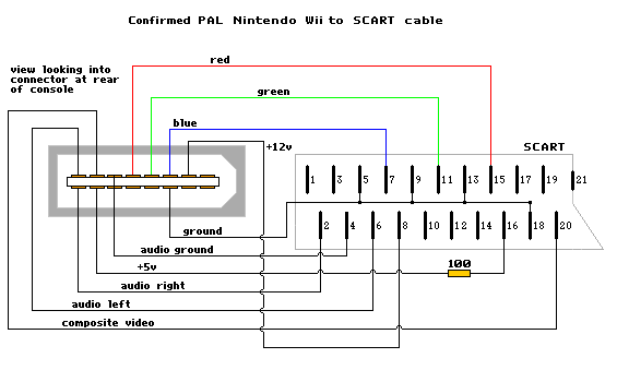
When I touch the GND wire, sometimes the signal returns, which seems kind of strange to me. So I took another look at this SCART adapter pinout:
Pin 5 is stated as "audio ground", explicitly...? In contrary to the previously found pinout tables where pin 5 is just "ground" or even "composite ground".
I will try to use pin 12 as GND to see if it makes any difference. In the meantime... just looking for some confirmation. Am I doing this completely wrong? Why are there different pinout tables?
Thanks.
EDIT: images too big
Recently, I've become the owner of a used Wii without power supply and cables. Infrared sensor bar is being replaced by candles (works great!
Right now, I am trying to connect my Wii mainboard to my TV without an original Nintendo a/v cable, but with wires, soldered to the connector pins. Using Google image search, apparently, there are various cables existing:


For the current state of my project, I'd only need composite video, no RGB, not even audio. Something similar to cable #3. So I looked for Wii a/v connector pinouts and found the following sources:
http://www.hardwarebook.info/Wii_A/V
http://pinouts.ru/Game/nintendo_wii_av_pinout.shtml
http://gamesx.com/wiki/doku.php?id=av:wii_multi_av_pinout
I decided to just use the "composite video" pin 3 and pin 5 for GND. You can see my work in this bad quality image:
However, it turned out to be kind of buggy. Sometimes there is no video signal at all. Sometimes it just gets lost after a minute or two. My soldering seems to be fine, jiggling and wiggling at the wire doesn't change a thing and continuity with multimeter checks out.
When I touch the GND wire, sometimes the signal returns, which seems kind of strange to me. So I took another look at this SCART adapter pinout:
Pin 5 is stated as "audio ground", explicitly...? In contrary to the previously found pinout tables where pin 5 is just "ground" or even "composite ground".
I will try to use pin 12 as GND to see if it makes any difference. In the meantime... just looking for some confirmation. Am I doing this completely wrong?
Thanks.
EDIT: images too big