Super mega finalized awesome AUDIO AMP DIAGRAM!

bentomo

Frequent Poster
Well emarassingly enough after some mistakes were caught and some degradation in quality over time I've decided to go back with the original components recommended by TI. I'm 99.9% sure that this diagram is error free and will give you the highest quality audio amp that this IC can deliver. Plus the option of a digital potentiometer for button pushing rather than using a massive chunky potentiometer to adjust the sound.

Capacitors are in micro farads. (µF)
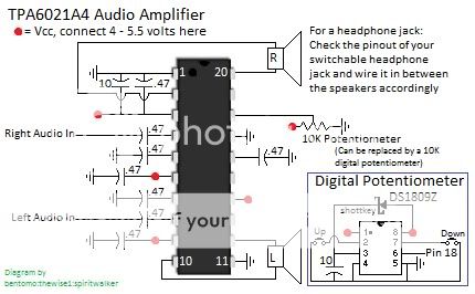
amp-Copy.jpg


SS used a 5 pin 10k pot from radioshack and it shorted out a gamecube momentarily, don't use those.

Try even a 15k pot if you want better volume control.
 
Missing the headphone circuitry. I am disappoint. For just speakers, though, thumbs up.
 
XCVG said:
Missing the headphone circuitry. I am disappoint. For just speakers, though, thumbs up.
Yes because the speakers in this circuit doesnt share a common ground like the ones in the headphones.
Thats why the IC have a pin for selecting between the speakers and the headphones, right?
 
There is no such pin, at least I don't see one in the datasheet.

Although frankly it doesn't matter, because you can wire up a headphone jack to any audio amp, in this case use common ground for the headphones ground, and then just use the speaker's L and R positive lines to the respective headphone lines.

Might have put some resistors on the headphone jack though, most amps put out too much for headphones and the sound is loud. Be careful not to put them between the amp and the actual speakers though, you might get it too quiet!

After I build this amp I'll add in a headphone jack diagram, assuming I can find a headphone jack... >.>

SS
 
Actually, the TPA6021 can drive headphones in a different mode. The datasheet describes how to wire it to automatically switch. Alternatively, wire the headphone switches inline with the positive output to the speakers and ground out the sleeve. It can't be good for either the amp or the headphones, but it should work.
 
XCVG said:
Actually, the TPA6021 can drive headphones in a different mode. The datasheet describes how to wire it to automatically switch. Alternatively, wire the headphone switches inline with the positive output to the speakers and ground out the sleeve. It can't be good for either the amp or the headphones, but it should work.
I've wired it like this before, I used to use the standard diagram but skipping that part of the circuit completely saves a lot of space and possible errors in the headphone wiring. I've found it cheaper to just use a switchable jack. I can't find a reason not to just use a switchable jack instead of using the auto switch built into the 6021. I don't recommend using the auto switch as far as I can tell.


If anyone has a reason for using it let me know please.
 
Why? Because in speaker mode, the amp is, uh, configured, I guess you could say, to drive low-impedance loads from both ends. I'm not exactly sure what wiring headphones in when the amp is in that mode will do, but it can't be good for either the headphones or the amp. When switched to the other mode, the amp is configured to drive higher-impedance loads from one end. That's the way I understand it, anyway. Read the datasheet.
 
do you really need all those caps connected to ground? or did i not get the schematic right?
 
The extra caps give you better quality basically, the circuit will work with out them but over time the quality will degrade.
 
Hmm... This thread is roughly a year old o.O
But I think I want to add my pic anyway ;)
1isN8.jpg


It wouldn't be bad for anything to wire the headphone jack like in this diagram, would it?

And what is the difference between a 'normal' capacitor and a smd capacitor?
 
It would be fine to wire the headphone jack that way.

And some capacitors are different from smd in the sense that they have polarity.
 
Quick question,

After examining both diagrams in this thread, is the 10uF capacitor used in Bentomo's diagram an electrolytic capacitor?

It is not marked up as such, but, in the subsequent TI diagram it notes at the bottom, that the 10uF is to be an electrolytic.

Also, talking of the headphone switch, isn't it simply a case, that when the switch line is shorted against a speaker +ive feed, it converts the speaker lines into one speaker line. Making the speaker -ve line redundant?
 
Back
Top