I've been working on this for a couple of days now, figured I'd put it out there to see if there's any interest.
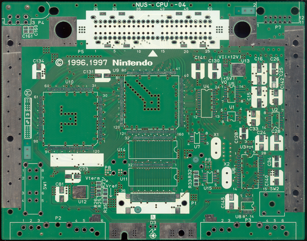
NUS-CPU-04 TOP
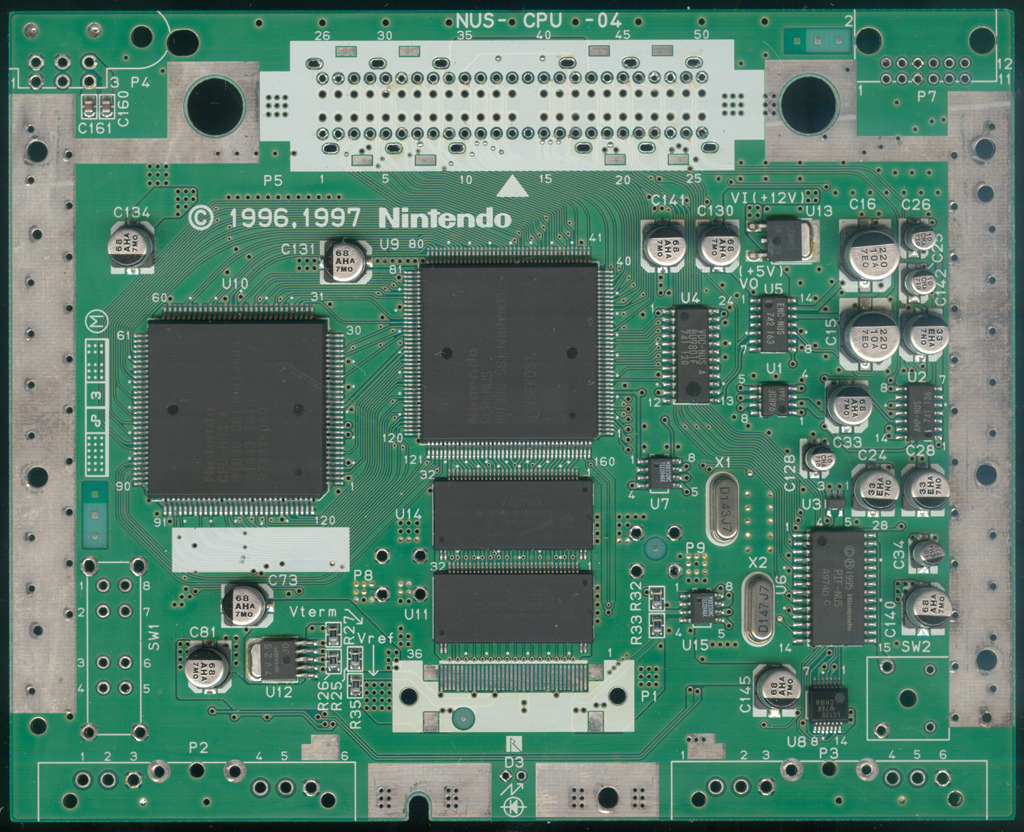
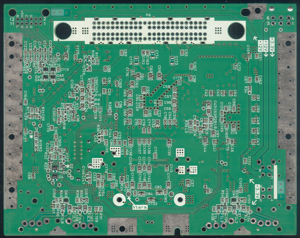
NUS-CPU-04 BOTTOM
NUS-CPU-04 TOP CLEAN
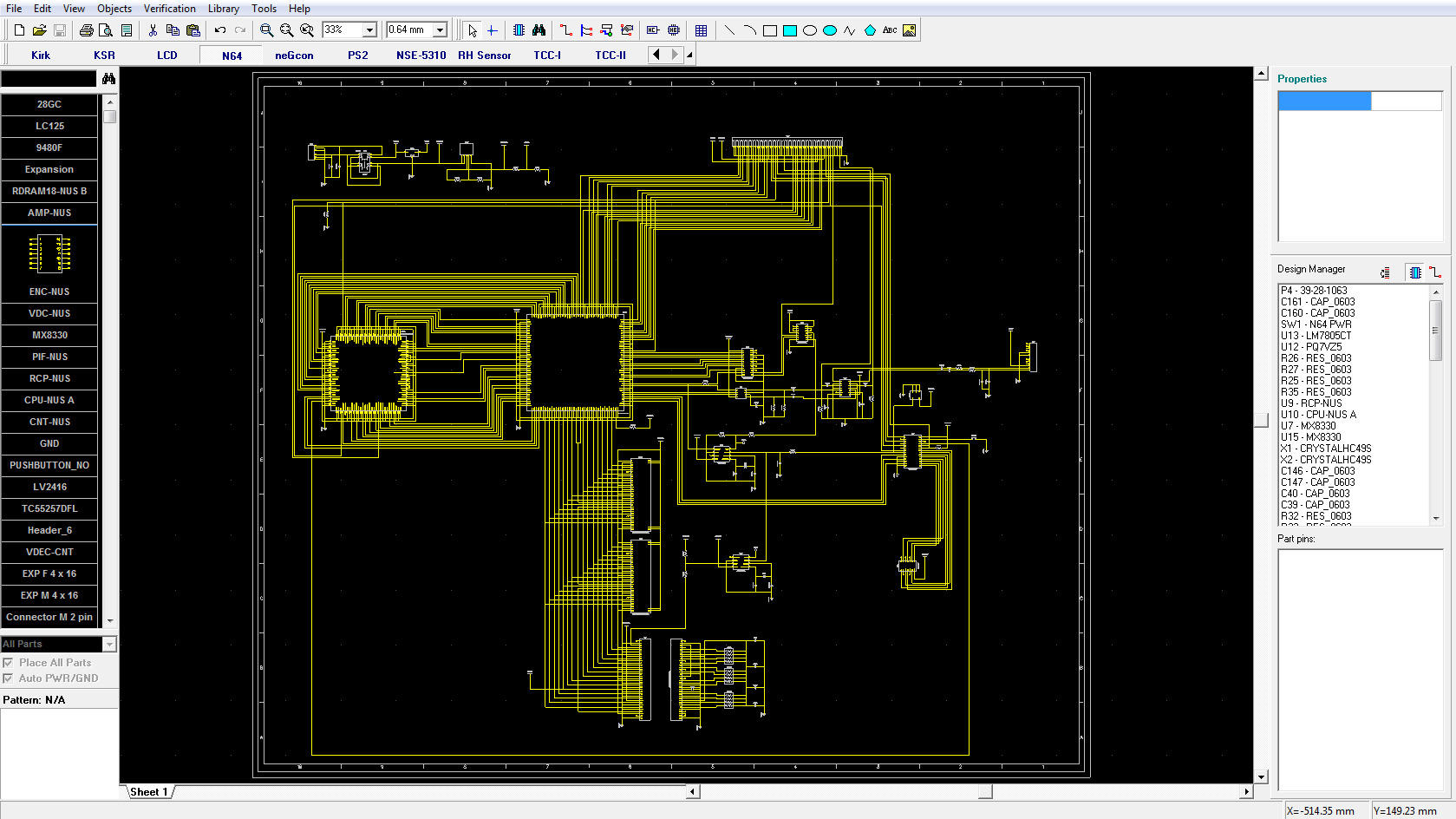
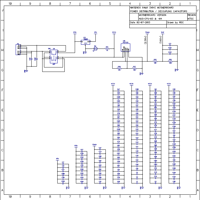
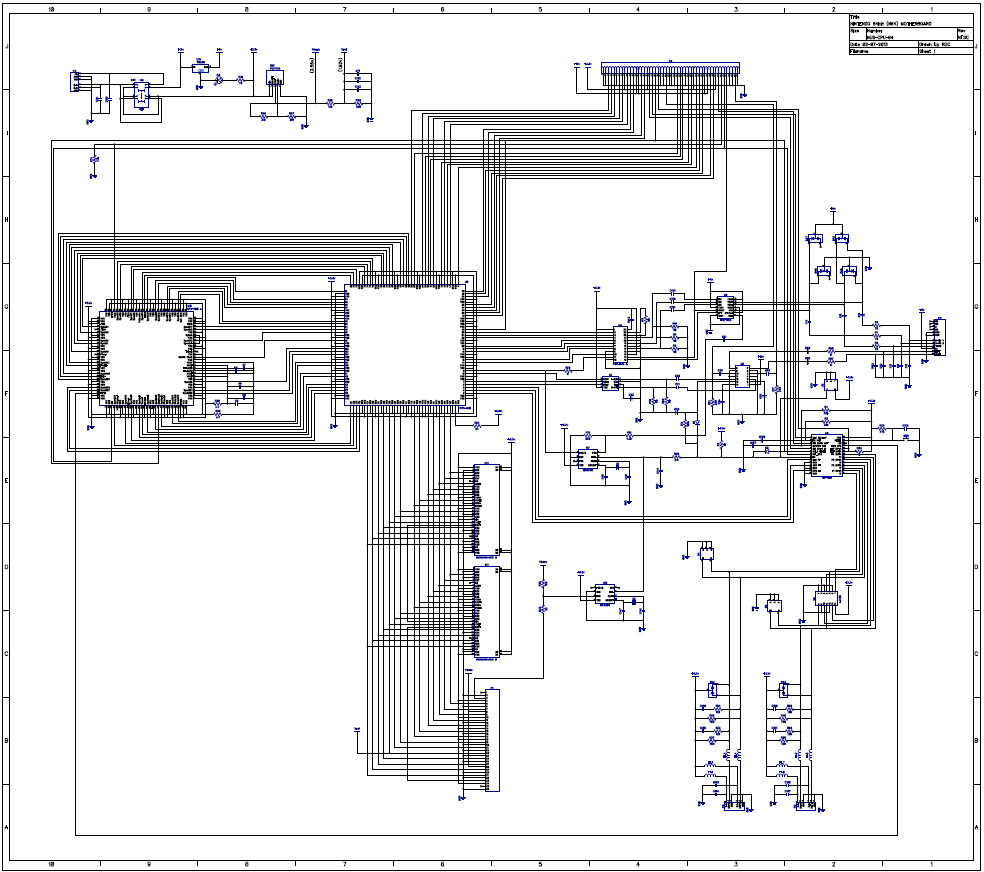
Right now it's pretty much done, just the Decoupling Caps on the 3.3v line need to be added and then everything gone over a few times for checking.
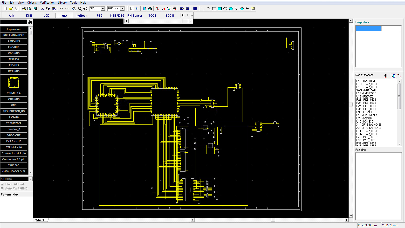
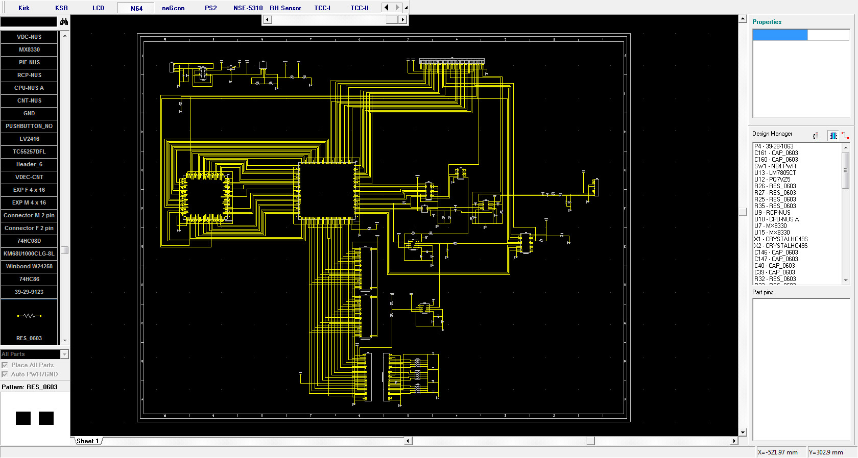
The PDFs of the 03 and 04 schematics as they are right now are here..
http://www.filedropper.com/n6403-04
The SMT Cap and Inductor values are not marked as that's a whole other thing to get into, I may do that at some point, but it's not on my list right now.
This is being done mainly just to do it. I may see how small I can remake the PCB at some point, though I'd prefer to do that with a CPU-08 or later version as it's already been 'updated' and has less components overall to deal with versus the older version boards.
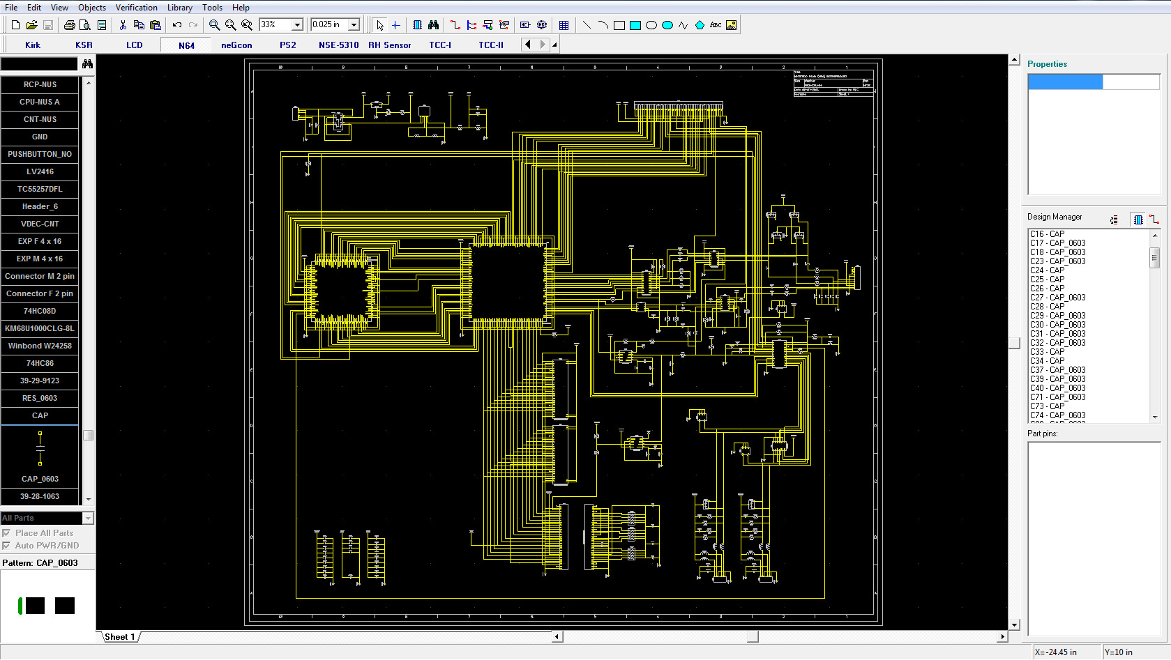
NUS-CPU-04 TOP
NUS-CPU-04 BOTTOM
NUS-CPU-04 TOP CLEAN
Right now it's pretty much done, just the Decoupling Caps on the 3.3v line need to be added and then everything gone over a few times for checking.
The PDFs of the 03 and 04 schematics as they are right now are here..
http://www.filedropper.com/n6403-04
The SMT Cap and Inductor values are not marked as that's a whole other thing to get into, I may do that at some point, but it's not on my list right now.
This is being done mainly just to do it. I may see how small I can remake the PCB at some point, though I'd prefer to do that with a CPU-08 or later version as it's already been 'updated' and has less components overall to deal with versus the older version boards.
Last edited: