This is the first in a great series of guides written by portable making extraordinaire Bacteria! In in, he details a few easy steps you can take to take apart and wire your PSone or Zenith game screen and prepare it for attaching to a portable!
Screen Modding Guide#1: Taking apart, Wiring and Preparation
Opening up an official Sony PSOne screen
This is what one looks like, and the arrows denote the screws you need to remove. Note, two screws are above the screen
under the rubber blocks and more screws under the speaker grills - lift out the grills with a small screwdriver.
http://i591.photobucket.com/albums/ss35 ... 64_008.png
Lift up, and use a screwdriver to pry the two pieces of plastic apart:
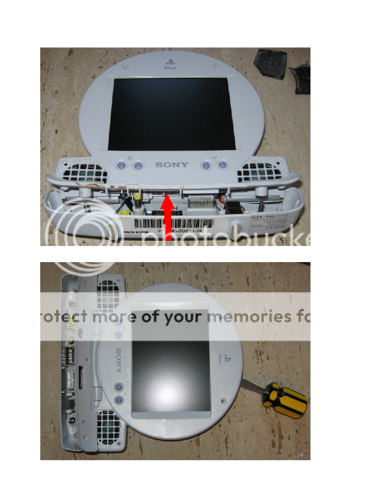
This reveals the board. When you undo the five screws in the mobo the screen below will lift off. The speakers can be
separated from the case by prying with a screwdriver.
Pry off the speakers from both sides of the case, and gently pull off the two plugs to remove them. Then, GENTLY lift off the brown tab to release the ribbon, so the screen can detach.
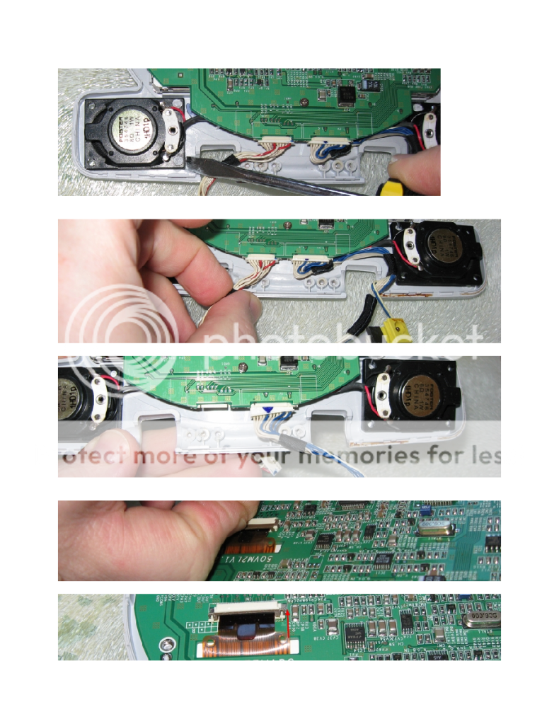
Put pliers onto the plug below to remove the connections to the screen. Be careful not to pull the wires!
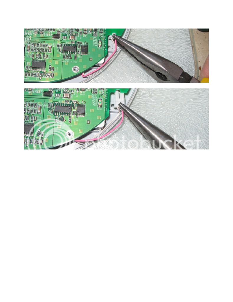
The reason for this is that it is far easier to work on the board with the screen removed, also, you can mount the screen far
easier into a case.
You may have noticed, my system is put onto a piece of glass; non conductive, easy to move about on desk; and also, put
the screen when working on the case onto an old cloth, to protect screen and case from scratches. My desk is covered in
self-adhesive floor tiles, which are also great as they are non-conductive.
Wiring a PSone/Zenith LCD:
This is what a PSone screen looks like, sat on its motherboard:
Ignore the brown area under the screen on the left part, the pic was taken from a blown board (not my doing!).
To power the screen when power is connected, a wire has to be connected to pin 12 socket 1 (see pic below) otherwise the
screen s light isn t getting any power so the screen will look really dark.
If, when the system is turned on, you get a white screen which gets progressively brighter until it turns off, that is because
there is no video signal going into the screen, ie you probably haven t connected it. Also, make sure you connect the ground
from your console to the PSone screen board.
I adapted existing pictures of the two pics below from other sites, no point re-inventing the wheel; however I have updated
the pics a bit with wiring diagrams:

If you are likely to use the screen for audio for both composite and RGB inputs, it is a good idea to connect the two left
audio connections together; and also the two right audio connections together.
Manufacture of these screens stopped a few years ago, however they are still quite easy to get hold of via e-bay. You can
use other screens of course, anything which takes composite input and about the right voltage. Modders like these screens
because they have a nice large 5" screen, good visual quality, versatile and take about 7v which is generally what most
console systems take.
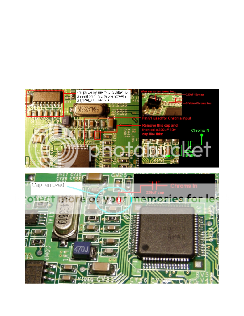
The PAL version of the official Sony PSone screen has the ability to input S-video, although doing this will stop it taking
composite and only be S-video and RGB. These are not my pics, they are from a fellow modder; I have tried the mod,
seems to work fine.
Screen Modding Guide#1: Taking apart, Wiring and Preparation
Opening up an official Sony PSOne screen
This is what one looks like, and the arrows denote the screws you need to remove. Note, two screws are above the screen
under the rubber blocks and more screws under the speaker grills - lift out the grills with a small screwdriver.
http://i591.photobucket.com/albums/ss35 ... 64_008.png
Lift up, and use a screwdriver to pry the two pieces of plastic apart:
This reveals the board. When you undo the five screws in the mobo the screen below will lift off. The speakers can be
separated from the case by prying with a screwdriver.
Pry off the speakers from both sides of the case, and gently pull off the two plugs to remove them. Then, GENTLY lift off the brown tab to release the ribbon, so the screen can detach.
Put pliers onto the plug below to remove the connections to the screen. Be careful not to pull the wires!
The reason for this is that it is far easier to work on the board with the screen removed, also, you can mount the screen far
easier into a case.
You may have noticed, my system is put onto a piece of glass; non conductive, easy to move about on desk; and also, put
the screen when working on the case onto an old cloth, to protect screen and case from scratches. My desk is covered in
self-adhesive floor tiles, which are also great as they are non-conductive.
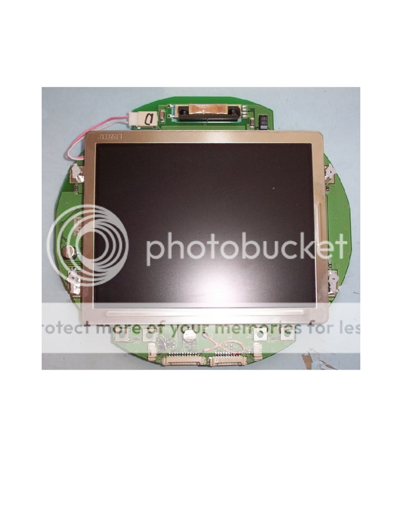
Wiring a PSone/Zenith LCD:
This is what a PSone screen looks like, sat on its motherboard:
Ignore the brown area under the screen on the left part, the pic was taken from a blown board (not my doing!).
To power the screen when power is connected, a wire has to be connected to pin 12 socket 1 (see pic below) otherwise the
screen s light isn t getting any power so the screen will look really dark.
If, when the system is turned on, you get a white screen which gets progressively brighter until it turns off, that is because
there is no video signal going into the screen, ie you probably haven t connected it. Also, make sure you connect the ground
from your console to the PSone screen board.
I adapted existing pictures of the two pics below from other sites, no point re-inventing the wheel; however I have updated
the pics a bit with wiring diagrams:
If you are likely to use the screen for audio for both composite and RGB inputs, it is a good idea to connect the two left
audio connections together; and also the two right audio connections together.
Manufacture of these screens stopped a few years ago, however they are still quite easy to get hold of via e-bay. You can
use other screens of course, anything which takes composite input and about the right voltage. Modders like these screens
because they have a nice large 5" screen, good visual quality, versatile and take about 7v which is generally what most
console systems take.
The PAL version of the official Sony PSone screen has the ability to input S-video, although doing this will stop it taking
composite and only be S-video and RGB. These are not my pics, they are from a fellow modder; I have tried the mod,
seems to work fine.