Protobug's second GCP

dark_samus said:
If you look at the calculations over at zenlocs thread you'll see that it's almost exactly the same as the stock regulator (if just a bit better) and takes longer for the voltage drop to affect the unit (since the GameCube regulator is made for a constant 12v source) which means you'll actually get longer out of the same batteries with zenlocs regs

Ok thanks i'll take a look :)


@Aurelio : Thanks ! i used a printer of a friend of mine which is a BCN3D+ :) it took about 10 hours to print
 
Thanks a lot :D !

I started modding a bit and wired my power regulator, but i don't get any image...
Am i missing something ? (i have to mention that i tested every connection and wire touching each other) The fan is running fine and the board is heating as normal
My screen works fine and i only get either a black screen (but with the screen turning on meaning that a signal is coming) or fuzzy scanlines ..


I didn't wire any audio yep because i haven't received my speakers yet.
Here is the Composite wiring (i tried both sides)

thanks for your quick answers :)
 
on the regulator board the second red wire from the top, i don't get 12V, i'm gonna try with a different regulator to see if it works .. other than that all seems pretty normal
 
i gave it 5V nothing changed. I tried a different regulator and even another board i had laying around i got the same results .. I'll try with another cable later..

Is my regulator wiring correct ?
 
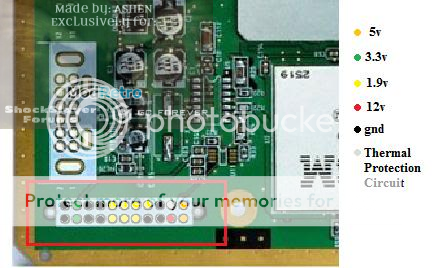
I'm not too sure to be honest, I would try bridging the 1.9V and 3.3V pins on the mobo.
14.png

this is top of mobo btw

EDIT: That was really badly formulated haha. bridge the the 5 1.9V pins together and the 2 3.3V pins together
 
I bridged everything and the dd seemed to react :) Which means my board isnt dead yet. But i still dont get any image . .. i'm gonna try again next weekend because i'm not home this week. Many thanks for the help :)
 
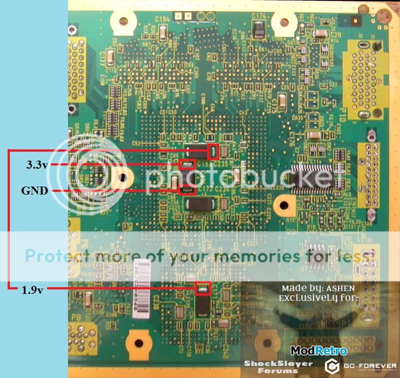
I would try wiring the 1.9v and 3.3v lines directly to the CPU and GPU as pictured below. If that doesn't work, I would also try replacing the resistor on your composite pcb with a potentiometer to test variable resistances. The resistance on your board may be too high, that could make your video signal too weak for your screen to display. What you can do is use a pot to see if you get a picture by adjusting it and then measure the resistance if/when you do get a picture, then simply replace the pot with a resistor with the appropriate resistance.

If neither of these two things work, then you may have a short somewhere on your board, your screen may not support a PAL signal or at worst the board could be bad.

Oh and I'm a 'he' by the way :p

16.png
 
Back
Top