Introduction
After I did a lot of DMG backlighting, biverting and GBC frontlighting I thought I'd give it a go and build my personal ultimate Gameboy - That's a GBASP inside a DMG's housing. I was inspired by people who did it before so this is nothing new, but I saw a lot of people asking for specific infos, so here it is...
Even if this might look like a step-by-step guide - it's NOT.
There are many ways to get this done, I'd like to share the way I did it, my joy and my frustration I've had with this project.
Please note: I'm not a native english-speaking person. If you find there's something that can be put better, please let me know. I will also update images with foreign text, so please have a little patience. Thanks!
Links
The mod
Ingredients:
Tools:
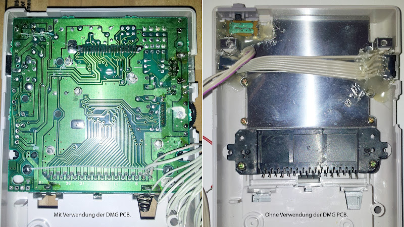
Here's a comparison:
left: with DMG-LCD-PCB
right: without
Different Gameboys, AGS-001 and AGS-101
AGS-001: Frontlight, (Light-Control On/Off)
AGS-101: Backlight, brighter (Light-Control Level1, Level2) [and Level 3 by patching the mainboard, see below]
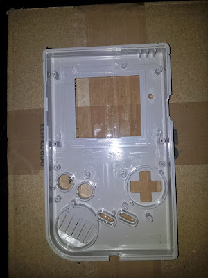
So, whatever GBASP you'll be using, you have to decide if you keep the plastic srew-mounting poles inside the DMG's front-housing or if you grind them off...
-keep'em:
>> + that's a clean solution as you'll be able to use the screws to close the thing in the end.
>> - you'll have to grind the mounting-poles as well as the screen as well as the mainboard to make it all fit.
-drop'em:
>> + so you have plenty of room to align the screen and the mainboard.
>> - well, then start thinking of a way to close that thing in the end...
Here's the AGS-001 Screen (Frontlight Model)
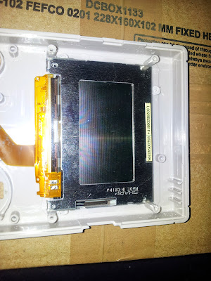
And the AGS-101 Screen (Backlight Model)
Whatever direction you chose to mount the GBASP pcb above the screen, you may also have to grind the mainboard a little.
Watch out for leads running on the upper AND lower side of the pcb!
The screen plus the mainboard will fit perfectly and there's still enough space for everything else.
Fuses
You may find that the GBASP's fuses blow. For example if you mess around with you wiring. Also ebay-junk or garage-sale gameboys often have blown fuses.
If you have a GBASP that seems to be dead you can try bridging the fuses and see if the screen comes up.
Fuse F2 >> fast-blowing, you should check this one first.
Fuse F1 >> not-so-fast-blowing, you should additionally check this one too if bridging or replacing F2 didn't help.
Replacement-Fuses:
Where are the fuses on the GBA SP?
Desoldering components
Prepare your GBASP and desolder these parts:
Battery-Transplant
Different grinding tools sure come in handy when dealing with the GBASP's plastic cover. Also a file for some finetuning will be neccessary.
In general we'll cut off the complete battery compartment of the GBASP and make it fit inside the DMG.
On the inner side, there's a passthrough for the battery-contacts: We want to keep this intact so we can mount the contacts without hussle.
The plastic-part with the contacts will raise the compartment by 2 Millimeters, you can easily make use of a piece of plastic to make it even.
The DMG's battery door will close smoothly and the GBASP's battery is seemlessly hidden inside.
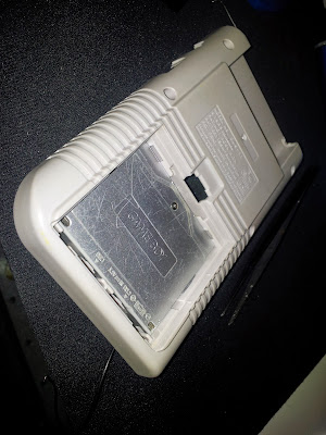
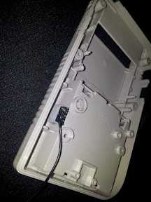
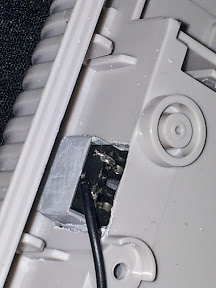
Inside the DMG we'll need to cut out a rectangle as a passthrough for the battery contacts.
Gameboy COLOR Mode
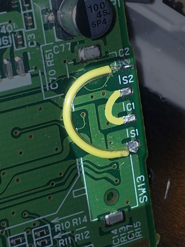
The switch right next to the cartslot reads SW13. GB and GBC cartridges are slightly larger than GBA carts so they will flip the switch when inserted.
If you short the connection you now have a Gameboy COLOR instead of a GBA.
POWER TO THE PEOPLE
Let's gain control over the On/Off-switch (SW1), that's easy because the DMG's respective switch acts in the same manner:

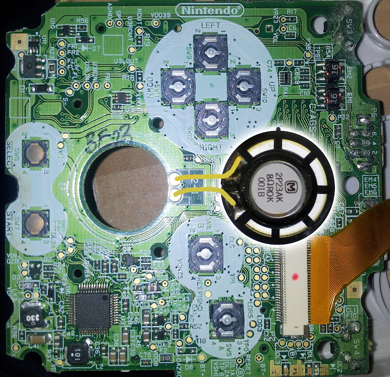
PLAY IT LOUD
Connecting the speaker is a breeze.
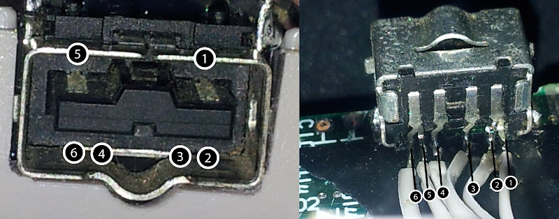
Ext.2 Connector
The EXT.2 port of the GBASP is used for charging the battery as well as connecting headphones when using an adaptor-cable.
External power input is used to charge the built-in battery, it cannot be used to run the SP without that battery.
You can mute the speaker when PIN5 connects to GND.
Now here comes the first tricky part:
The original DMG's headphone jack has a switch inside which is 'normally closed'. It closes 2 contacts when it's NOT plugged. When you plug a 3,5mm jack the connection is open.
This is of course contrary to the EXT.2 port's logic... because it closes the connection between PIN5 and GND to mute the speaker while being 'normally opened'.
The original DMG's headphone jack holds another challenge if you'd like to re-use it. There are parts and connetions that might not be suitable for your wiring. BUT... it comes with nice mountings and therefor it might be worth keeping it.
Here's the pinout of the DMG's headphone jack:
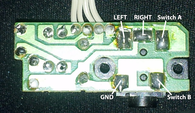
If you want to use that part make sure its connections suit your needs.
Other creative solutions for getting sound:
Pictured is a jack from a MGB (Pocket).
Source: Nex >> http://chipmusic.org/forums/topic/1443/ ... pro-sound/
Volume potentiometers
Specs of the DMG's thumbwheel (b10KOhms):
The DMG's contrast-pot has 30K, you may or may not be able to use that as a volume control.
This diagram is courtesy of benheck-forum member ModGyver:
This works really well.
The GBASP seems to control the volume internally depending on what resistance the volume-slider is giving.
On the DMG it works completely analogue: 2 inputs, 2 outputs, 1 GND.
RESET
Inside the GBASP there's a reset-trigger! If you connect it to GND the device will reboot immediately.
That's awesome, if you have a "GB USB SmartCard 64M" where you can switch the game-selection pages by switching off and on very quickly, I think resetting is much more comfortable.
I've used a switch from an old TV-chassis that fits quite well.
Link Port EXT.1
The pins are labeled on the GBASP mainboard. Simply connect all pins to the connections on the board.
Buttons and D-Pad Hijacking
Now, to hijack the controls and make use of the DMG's dpad and buttons there are different ways to do it....
Just make sure the carbon-pads underneath the buttons are making contact to the pcb when pressed.
Either you cut your DMG's lcd-pcb like this:
...or you build something on your own...
OR you can use one of these 'common ground pcbs' that board-member 'micro' made available here -> http://circuit-board.de/forum/viewtopic.php?f=56&t=9847
You may use both PINs 6 of the EXT.1 and EXT.2 ports - there are countless more GND connections to be used for this.
LEDs
All the LEDs have 1,9V inputs.
For relocating either solder wires directly to the LED's contacts or use these pads:
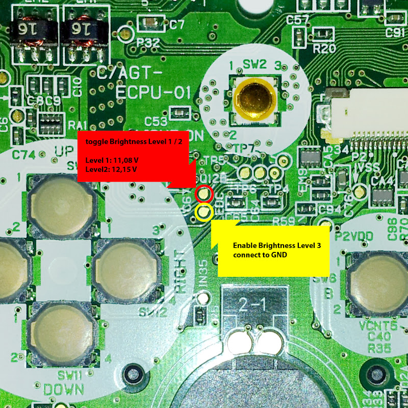
Brightness control (only AGS-101)
Connecting the DMG's cartslot
I've use a heatgun to optain the cartslot from the pcb. The connection is simple yet time-consuming:
If you made it till here use some hot glue to keep the wires flat and in place.
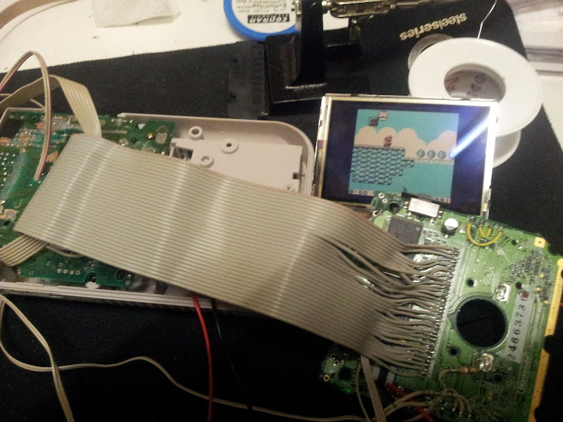
I know it's getting tight inside but it'll work...
After I did a lot of DMG backlighting, biverting and GBC frontlighting I thought I'd give it a go and build my personal ultimate Gameboy - That's a GBASP inside a DMG's housing. I was inspired by people who did it before so this is nothing new, but I saw a lot of people asking for specific infos, so here it is...
Even if this might look like a step-by-step guide - it's NOT.
There are many ways to get this done, I'd like to share the way I did it, my joy and my frustration I've had with this project.
Please note: I'm not a native english-speaking person. If you find there's something that can be put better, please let me know. I will also update images with foreign text, so please have a little patience. Thanks!
Good to know:
In this we'll be locking the GBA into GameBoy Color Mode. Also we'll be using the DMG's cartslot. This means there's no way GBA cartridges will run on this thing - so there's no need to install "L" and "R" buttons. This is supposed to be my ultimate GameBoy, not the ultimate GBA.
think of it as a screen-upgrade for your old friend...
Links
- My Picasa-Gallery with all the fullsized pictures:
https://picasaweb.google.com/1159487454 ... directlink
- Get a controller-PCB from KITSCH-BENT:
http://store.kitsch-bent.com/
- DMG PCB with Common-Ground: (german site, sorry, I'll lead you through it if you ask nicely)
http://circuit-board.de/forum/viewtopic ... 89#p226489
- Source of inspiration: Michael J Moffit's Site
http://mikejmoffitt.com/wp/?p=123
- GBA Hardware Documentation:
http://nocash.emubase.de/gbatek.htm
The mod
Ingredients:
- Gameboy DMG
- Gameboy Advance SP (we only need the mainboard and the screen)
Tools:
- (De-)solder-utilities
- Multimeter
- Dremel or rotary tool
- Hot glue gun
- Duct tape
- Some flexible wires
Code:
Checkpoint
At this point you might be excited and just want to start modding - but wait! As I said, there are many way of doing this. Here's the first choice you'll have to make:
You EITHER keep the DMG's lcd-pcb OR you don't and find yourself fiddling around with power-switches, volume-wheels and other components that have to be mounted within the DMG's housing.

-you decide to keep the pcb
>> + then you don't have to worry about mounting components.
>> - then you might have a hard time closing the device in the end.
>> - then you have to freestyle-mount the EXT.2 Connector of the GBA

-you decide to ditch the pcb
>> + then you'll have a lot more space inside the case.
>> - you habe to do more soldering and glueing.
Here's a comparison:
left: with DMG-LCD-PCB
right: without
Different Gameboys, AGS-001 and AGS-101
AGS-001: Frontlight, (Light-Control On/Off)
AGS-101: Backlight, brighter (Light-Control Level1, Level2) [and Level 3 by patching the mainboard, see below]
So, whatever GBASP you'll be using, you have to decide if you keep the plastic srew-mounting poles inside the DMG's front-housing or if you grind them off...
-keep'em:
>> + that's a clean solution as you'll be able to use the screws to close the thing in the end.
>> - you'll have to grind the mounting-poles as well as the screen as well as the mainboard to make it all fit.
-drop'em:
>> + so you have plenty of room to align the screen and the mainboard.
>> - well, then start thinking of a way to close that thing in the end...
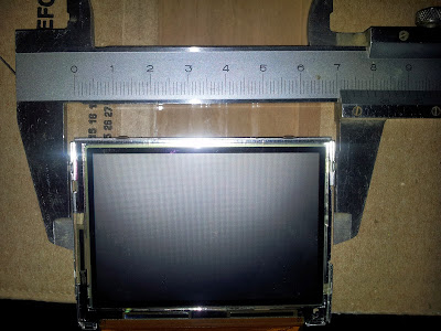
Info:
If you grind the mounting-poles a little, there's a horizontal space of exactly 7,2 cm
Here's the AGS-001 Screen (Frontlight Model)
And the AGS-101 Screen (Backlight Model)
Whatever direction you chose to mount the GBASP pcb above the screen, you may also have to grind the mainboard a little.
Watch out for leads running on the upper AND lower side of the pcb!
The screen plus the mainboard will fit perfectly and there's still enough space for everything else.
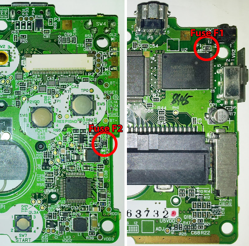
Fuses
You may find that the GBASP's fuses blow. For example if you mess around with you wiring. Also ebay-junk or garage-sale gameboys often have blown fuses.
If you have a GBASP that seems to be dead you can try bridging the fuses and see if the screen comes up.
Fuse F2 >> fast-blowing, you should check this one first.
Fuse F1 >> not-so-fast-blowing, you should additionally check this one too if bridging or replacing F2 didn't help.
How can you tell if a GBASP has a blown fuse?
-It doesn't power on.
-If you connect the power-supply, LED3 (orange) will light up and goes out immediately.
Replacement-Fuses:
Code:
    FUSE, FAST ACTING, SMD, 250MA
    Voltage Rating AC:32V
    Voltage Rating DC:24V
    Fuse Current Rating:250mA
    Fuse Size Code:1.6mm x 0.81mm x 0.48mm
    Fuse Type Blowing Characteristic:Fast Acting
    Series:1608FF
    SMD Fuse Case Style:0603
    Approval Bodies:UL, CSA
    Case Style:0603
    Colour Code:Green
    External Length / Height:1.6mm
    External Width:0.8mm
    Overall Height:0.48mm
    Overall Length:1.6mm
    Typ Resistance @ 10% Rated Current:3ohm
    Voltage Drop @ Rated Current:0.9V
    Breaking Capacity Current DC:35A
    Fuse Breaking Capacity:50A @ 32VDC
    Fuse Breaking Capacity Voltage DC:24V
Where are the fuses on the GBA SP?
Desoldering components
Prepare your GBASP and desolder these parts:
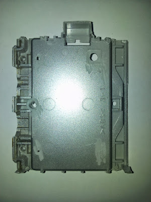
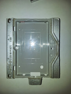
Battery-Transplant
Info:
The available space inside the DMG's battery compartment is exactly 5,75 x 5,0 cm
Different grinding tools sure come in handy when dealing with the GBASP's plastic cover. Also a file for some finetuning will be neccessary.
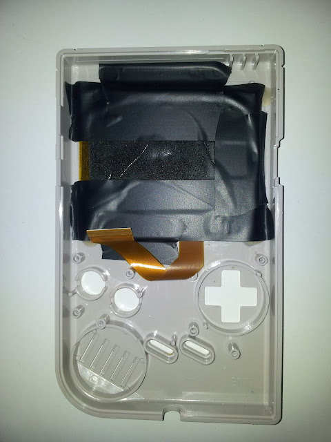
In general we'll cut off the complete battery compartment of the GBASP and make it fit inside the DMG.
On the inner side, there's a passthrough for the battery-contacts: We want to keep this intact so we can mount the contacts without hussle.
The plastic-part with the contacts will raise the compartment by 2 Millimeters, you can easily make use of a piece of plastic to make it even.
Info:
Inside the DMG's battery compartment we need an even surface, so the battery separators have to go.
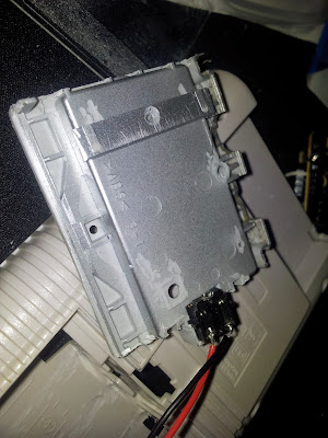
The DMG's battery door will close smoothly and the GBASP's battery is seemlessly hidden inside.
Inside the DMG we'll need to cut out a rectangle as a passthrough for the battery contacts.
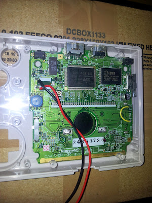
Info:
(upper picture: back of DMG)
Bottom: GND (black cable)
Top: power (red cable)
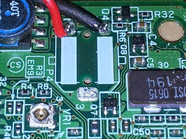
(lower picture: GBASP pcb)
Top: GND (black cable)
Bottom: power (red cable)
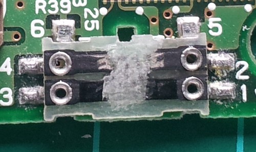
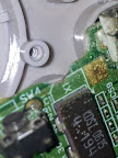
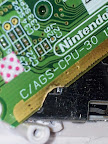
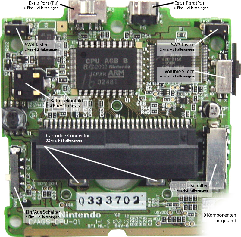
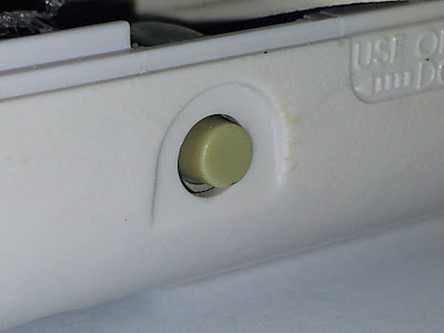
Gameboy COLOR Mode
The switch right next to the cartslot reads SW13. GB and GBC cartridges are slightly larger than GBA carts so they will flip the switch when inserted.
If you short the connection you now have a Gameboy COLOR instead of a GBA.
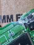
Info
C1 VDD35 (to S2 when PRESSED, to S1 when RELEASED)
S1 VDD3 (to C2 when PRESSED, to C1 when RELEASED)
C2 IN35 (to S1 when PRESSED)
S2 VDD5 (to C1 when PRESSED)
The outer contacts C2 and S1 will enable GBC mode.
The inner contacts S2 und C1 will supply 5V to PIN1 on the cartslot, that's important because many games make use of this for stuff like bankswitching etc.
POWER TO THE PEOPLE
Let's gain control over the On/Off-switch (SW1), that's easy because the DMG's respective switch acts in the same manner:
Info:
Pinout SW1 (power switch) GBASP
1 via 50Ohm Resistor to GND (OFF)
2 VS (BT+) (ON)
C VCC (to Board)
Do NOT only connect the ON-state! If you do that you either have to take out the battery or connect PIN1 to GND with a 50Ohms resistor or the GBASP will not power on again until you do either of both.
PLAY IT LOUD
Connecting the speaker is a breeze.
Code:
Checkpoint:
-GBASP Mainboard makes contact to the battery
-You should be able to hit the power switch and see the green lighted LED.
-You should hear the typical Gameboy COLOR boot-sound 'DeeDing'.

Tips:
Now would be a good time to reconnect the LCD-screen and align its position for a centered image. Use some hot glue to make it stay there-
Ext.2 Connector
:!: While relocating the port just make sure to connect every pin to its corresponding connection on the mainboard.
The EXT.2 port of the GBASP is used for charging the battery as well as connecting headphones when using an adaptor-cable.
External power input is used to charge the built-in battery, it cannot be used to run the SP without that battery.
You can mute the speaker when PIN5 connects to GND.
Code:
GBA SP and NDS - Power/Headphone Socket (EXT.2)

  Pin SP   NDS  Expl.
  1   P31  SL   Audio LOUT                          _____________
  2   P32  VIN  Supply Input (DC 5.2V)           SW| 5   ___   1 |SL
  3   P33  SR   Audio ROUT                         | ----   ---- |
  4   P34  SG   Audio GND (via 100uF to GND)       |_6__4   3__2_|
  5   P35  SW   Audio Speaker Disable (GND=Dis)    GND SG\_/SR VIN
  6        GND  Supply GND
  Shield        GND
Code:
Tip Audio Left ___ ___ _____+-----------+
Middle Audio Right (___|___|_____| |
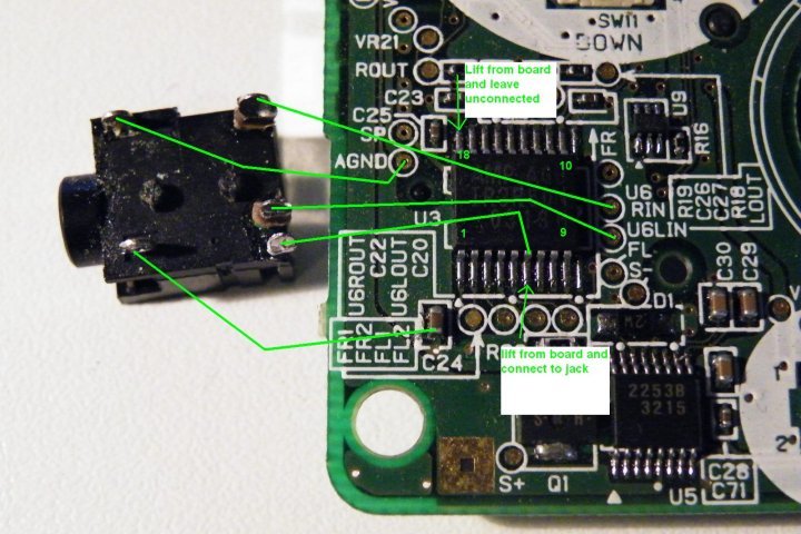
Base Ground L R GND +-----------+Now here comes the first tricky part:
The original DMG's headphone jack has a switch inside which is 'normally closed'. It closes 2 contacts when it's NOT plugged. When you plug a 3,5mm jack the connection is open.
This is of course contrary to the EXT.2 port's logic... because it closes the connection between PIN5 and GND to mute the speaker while being 'normally opened'.
The original DMG's headphone jack holds another challenge if you'd like to re-use it. There are parts and connetions that might not be suitable for your wiring. BUT... it comes with nice mountings and therefor it might be worth keeping it.
Here's where anyone who does this mod has to find his own way of dealing with how to use the sound. Sure a lot of you guys have plenty of different headphone jacks laying around, others might find it better to mess around with DMG's headphone jack while others just use a veroboard and build something on their own...
Here's the pinout of the DMG's headphone jack:
If you want to use that part make sure its connections suit your needs.
Other creative solutions for getting sound:
Pictured is a jack from a MGB (Pocket).
Source: Nex >> http://chipmusic.org/forums/topic/1443/ ... pro-sound/
Volume potentiometers
:!: I don't have the pinout of the GBASP's Volume-Slider (VR2).
If you know the pinout please post it here!
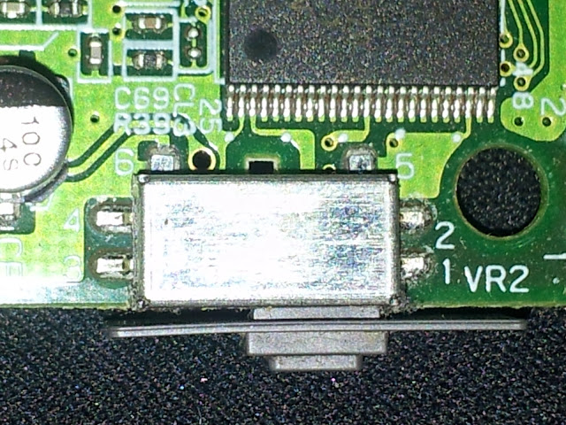
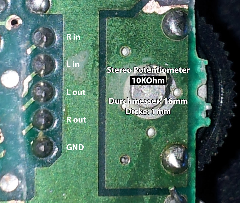
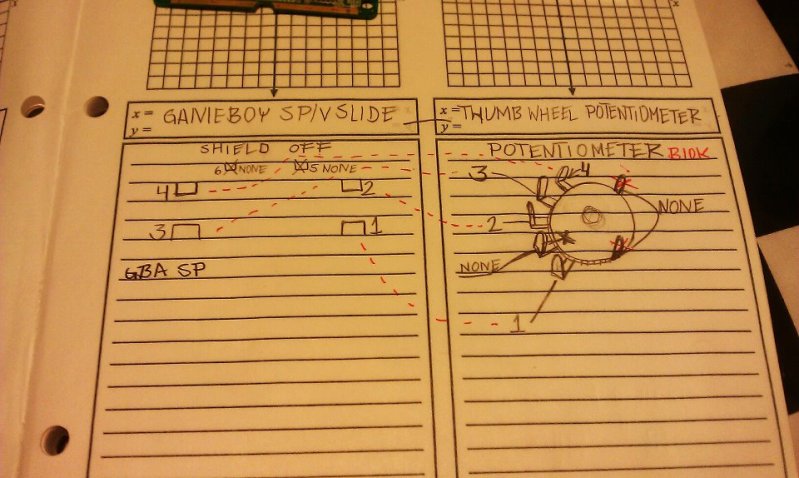
Specs of the DMG's thumbwheel (b10KOhms):
The DMG's contrast-pot has 30K, you may or may not be able to use that as a volume control.
This diagram is courtesy of benheck-forum member ModGyver:
This works really well.
The GBASP seems to control the volume internally depending on what resistance the volume-slider is giving.
On the DMG it works completely analogue: 2 inputs, 2 outputs, 1 GND.
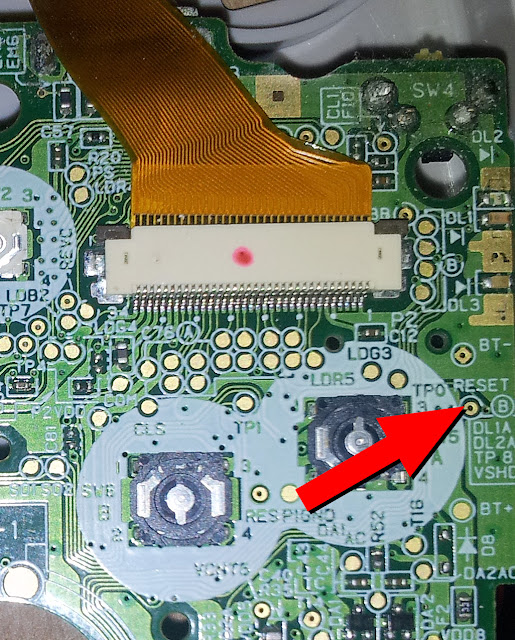
RESET
Inside the GBASP there's a reset-trigger! If you connect it to GND the device will reboot immediately.
That's awesome, if you have a "GB USB SmartCard 64M" where you can switch the game-selection pages by switching off and on very quickly, I think resetting is much more comfortable.
I've used a switch from an old TV-chassis that fits quite well.
Link Port EXT.1
Code:
Serial Link Port Pin-Out (GBA:"EXT" - GBA SP:"EXT.1")

  Pin  Name  Cable
  1    VDD35 N/A       GBA Socket     GBA Plug   Old "8bit" Plug
  2    SO    Red       ___________    _________    ___________
  3    SI    Orange   |  2  4  6  |  / 2  4  6 \  |  2  4  6  |
  4    SD    Brown     \_1_ 3 _5_/   \_1_ 3 _5_/   \_1__3__5_/
  5    SC    Green         '-'           '-'
  6    GND   Blue      Socket Outside View / Plug Inside View
  Shield     Shield
The pins are labeled on the GBASP mainboard. Simply connect all pins to the connections on the board.
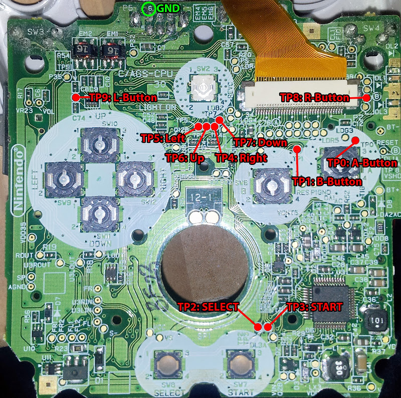
Buttons and D-Pad Hijacking
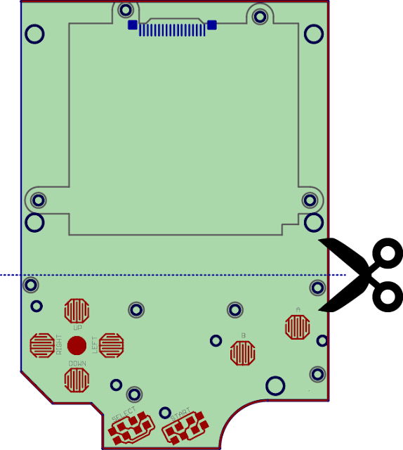
Now, to hijack the controls and make use of the DMG's dpad and buttons there are different ways to do it....
Just make sure the carbon-pads underneath the buttons are making contact to the pcb when pressed.
Either you cut your DMG's lcd-pcb like this:
...or you build something on your own...
OR you can use one of these 'common ground pcbs' that board-member 'micro' made available here -> http://circuit-board.de/forum/viewtopic.php?f=56&t=9847
If you cut the lcd-pcb you will have to re-route the leads for common ground!
Every pad on the pcb has to be wired to it's counterpart on the GBASP and its twin goes to GND.
You may use both PINs 6 of the EXT.1 and EXT.2 ports - there are countless more GND connections to be used for this.
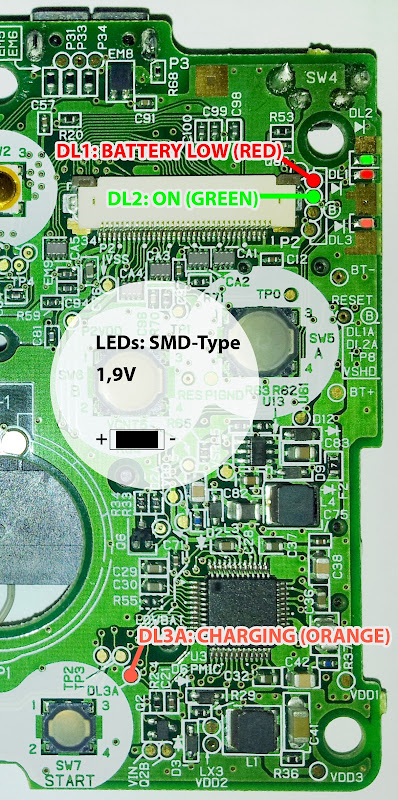
LEDs
All the LEDs have 1,9V inputs.
For relocating either solder wires directly to the LED's contacts or use these pads:
Brightness control (only AGS-101)
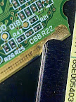
Connecting the DMG's cartslot
I've use a heatgun to optain the cartslot from the pcb. The connection is simple yet time-consuming:
Pin1 on the GBA geos to Pin1 on the DMG
Pin2 on the GBA geos to Pin2 on the DMG
Pin3 on the GBA geos to Pin3 on the DMG
....
Pin32 on the GBA geos to Pin32 on the DMG
If you made it till here use some hot glue to keep the wires flat and in place.
I know it's getting tight inside but it'll work...
-Have Fun-
-Alex-
-Alex-