Downing's CPU/Retro-Gaming Desk

Made do with what you have! I've had this desk and computer for awhile now so the most expensive parts of the system were already bought and paid for a long time ago. PS2 is my first one which is quite old now as well. X-box was free, had the plastic, had the Nintendo systems...but all in all if you broke it down to what I originally paid for everything (computer included) it was probably up to about 4 grand by now! But realistically all I've probably put into it since the project started was about $250 bucks or so for parts. Not bad really. Have to rewire the N64 and maybe the SNES too. Redesigning the way the systems are going to be laid out which forces me to do a bit of trimming to make it work. But it's going to be cool in it's own right, not to mention it being an add-on to something bigger!
 
These pics were taken earlier this week, but I'm making a great deal of progress with the Nintendo system box. I had to make some changes from the original design but they are working out better and will be worth the extra work.

First off, I had to replace the NES with a new clone as I pretty much ruined the last one in every way-shape and form. However it tuned out to be a blessing as this new set-up did not require me to relocate the NES cart slot! The pic below shows how I was able to mount the entire system to the box only having to rewire say 20 wires instead of 70 X 2.
IMAG0343.jpg


I do however have to do more work to the N64 as a result, including trimming which I've already done and relocating of the power and removal of the A/V out jack. Though this really didn't matter as I am funneling all the video and audio lines into one line respectivily.
IMAG0342.jpg


But all in all it's coming out good. I've got a good plan I think to wire everything up nice and clean and easially disconnectable if I ever have to move it. I hope to have the N64 done by tonight and then I can do some testing to make sure the box works, then I can spruce it up a bit!
IMAG0345.jpg
 
More Progress!!!

Finished wiring up the N64 cart, power and signal out. Still have cover the wire splices with tape and to connect a couple ground wires but for all general purposes it's complete.
IMAG0346.jpg


Here is the view of all three units secured and mounted in the box and all carts wired to their respective systems. This will then be wrapped in plastic on the front and right side with a plastic cover.
IMAG0347.jpg


Again from another angle
IMAG0348.jpg


I'm going to leave the back open as no one is going to see it and it makes for better ventilation and access to the systems if I need to!
IMAG0349.jpg


It might be too soon to tell but I'm thinking the hardest part is over. Now comes the fun part of wiring all the systems together so they all go through the VGA converter, but in theory this should work fine. I feel this really starting to come together!
 
Sunday was a blur of modding, I got so much done! Pretty much all that's left now is to wire up the video/audio and power to the control panel.

The pics below show my solution to the controller wire issues. I wanted to be sure that everything was quickly detatchable from the control box which would allow me to seperate the control box with the Nintendo systems as my computer fans run from the control box, so that needs to be in place at all times. But this way I can quickly disconnnect the Nintendo systems from the desk entirly without hassel. I used a 50 pin header and socket and it's been working out wonderfully. Still need to test the systems though and I should get that done tonight.


IMAG0350.jpg


IMAG0351.jpg


I glued a back plate of plastic inbetween the two layers of wires as this helps as a strain relief on the solder joint. A big problem I was having when everything was connected directly was the wires breaking from all the tweaking and moving of the system I did. This helps as well as closing it in with electrical tape.
IMAG0352.jpg


IMAG0353.jpg


IMAG0354.jpg


IMAG0355.jpg


I also put a 10-pin header and socket for the tact switches to the VGA converter. I'm hoping the wires aren't too long but where as this is just a normal momentary tact switch extension for something that isn't going to be pressed too often, I'm not overly concerned. If it's too long, I just shorten the wires, easy enough.
IMAG0356.jpg
 
So if you can tell what's going on in the photos below I give you credit! But all that's left for wiring is the A/V for all 5 systems. The only issue I see myself running into with that is that all the lines have to be funneled into one composite to S-video converter cable and that S-Video cable into the VGA converter! Though I have a few ideas how to make this work, I won't be able to tell until everything is together and I give it a go.

As for the power, all the switches are wired up with quick connects so if I need to disconnect the face plate, everything is easily dis-connectable. However the power for the N64 with it's two voltages kinda screwed me up a bit so I had to use a step down regulator and wire directly instead of using the stock power brick. But that's ok.

Hopefully another couple weeks and this will be done! Still have a lot of aesthetic work to do on both the control box and the desk itself, but I'll get there!

Things are a lot more cluttered in there now but soon enough there will be order in all this chaos!
IMAG0360.jpg


The audio switch wired up to the header, again dis-connectable if need be.
IMAG0361.jpg


IMAG0366.jpg


IMAG0367.jpg
 
I love it.
I remember when i was a kid i wanted to build a computer inside a desk but my dad said it was a dumb idea LOL.

Seriously though. Pimpin desk.
 
Sorry it's been awhile since an update! I've been exceptionally busy though, working on my desk as well as finally getting parts of my new vacuum former built!

But below are pics of my most recent progress with the computer desk. I've started/finished the front half of my controller that will control all three Nintendo systems that I've got on that platform. As before, that platforms will be on a roller slide, so I'll be able to pull it out of the desk face, insert a game directly into the systems and power it on via the control top mounted box which is also where the controller will be plugged in via Parallel port. The parallel port will but connected to a junction strip which will branch out to each individual controller PCB.

I may end up having to put an additional ground break switch under each system's power switch in case the signal tends to go to the other controllers as well, but we'll see when I get that far.

IMAG0666.jpg


IMAG0667.jpg


IMAG0668.jpg


IMAG0669.jpg


IMAG0670.jpg


IMAG0671.jpg


Again, not very happy with the finish on this but I've got some cool decals in mind which should cover the imperfections nicely.

Thanks again to all those who joined me on my chat channel as well! It's a great deal of fun!
 
Significant update for today. Between today and Friday I've managed to get a final layout for the controller as well as start the wiring process. I'm waiting on 5 or 6 SNES controllers to come in the mail so I can put one of the boards into the controller so then I have all three ready to go.

Before I go on I'd just like to thank everyone who showed up for my web session today though. Had Akari and Shock Slayer live with the video feeds and Conker, Electro Modder and Skullkid setting in during chat. That's really an awesome way to spend an afternoon, just modding and chatting. Again, look to the Tiny Chat thread to see when I'm on, or subscribe to the topic or me on twitter because I make a post every time I get on. It's a lot of fun!

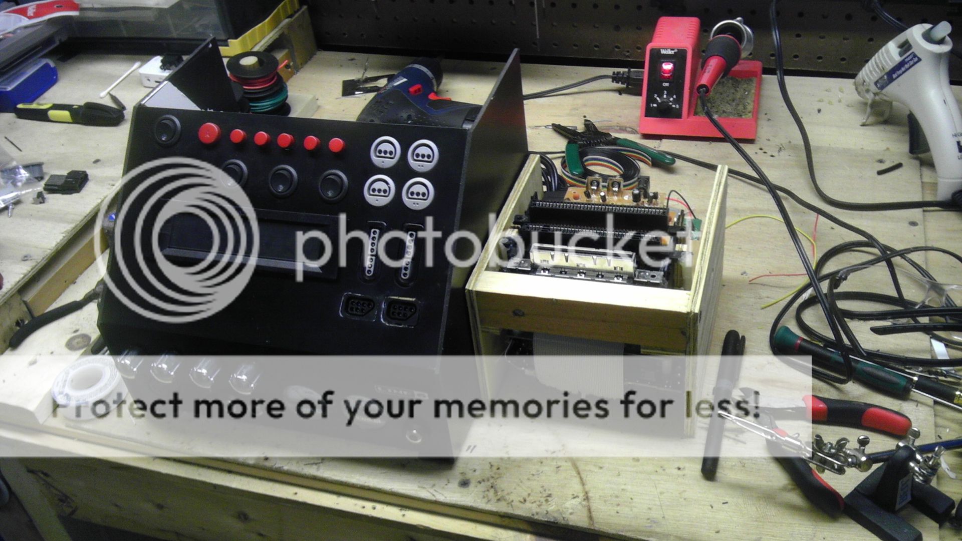
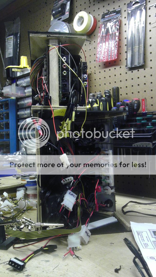
But getting back to the project, I made a major design change with the controller which included having the controller boards right in the handset itself as opposed to being in a separate box inside the desk. I did this because I got to thinking that the resistance from the button presses having to travel 6+ feet and then go 6 feet back to register just wasn't worth the risk. Keeping the controller boards within just a few inches is a much better way to go about, but I had to make the controller a bit thicker as a trade-off. However, the controller is still only 1.5" (36mm) thick and is quite comfortable.

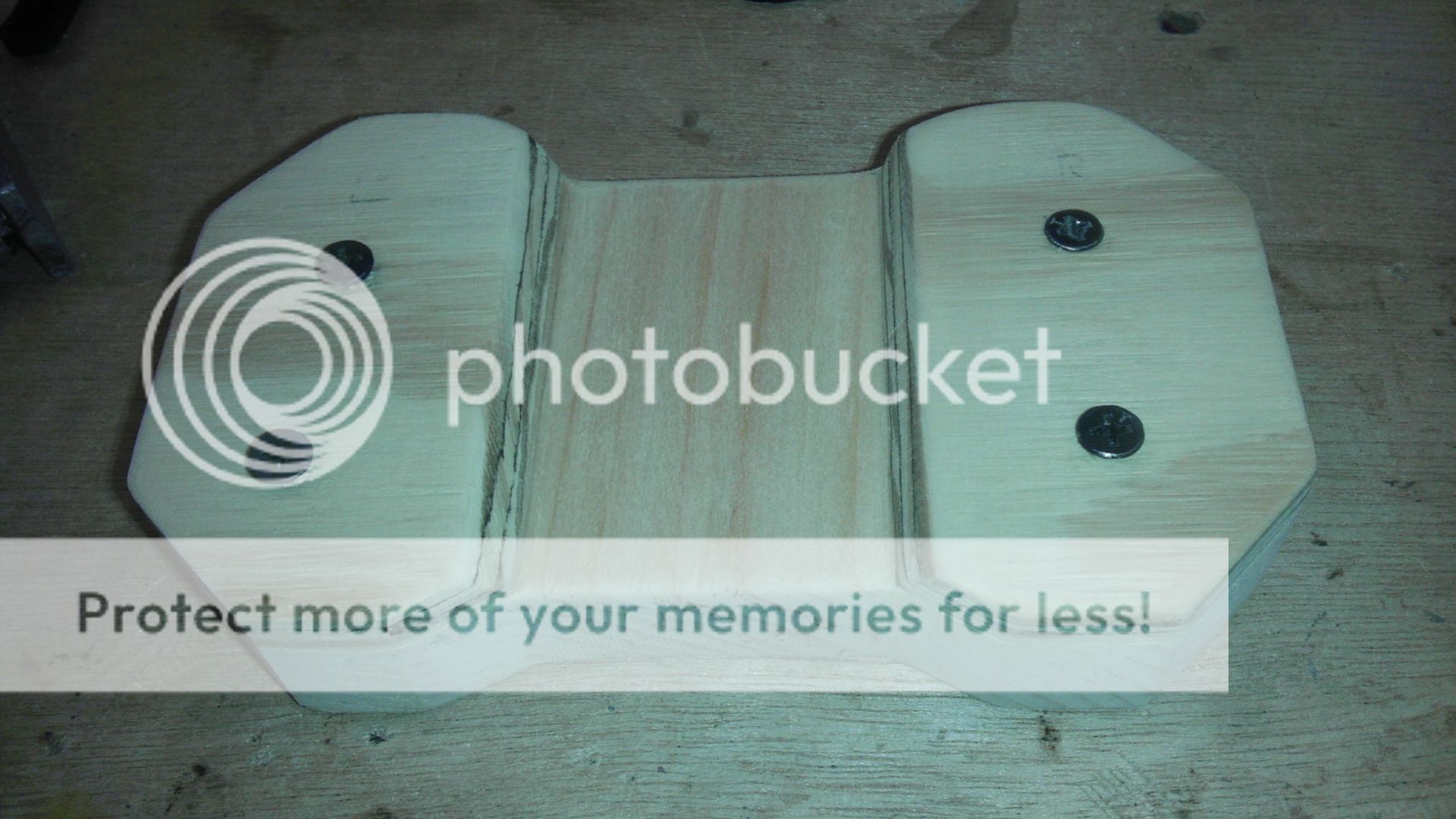
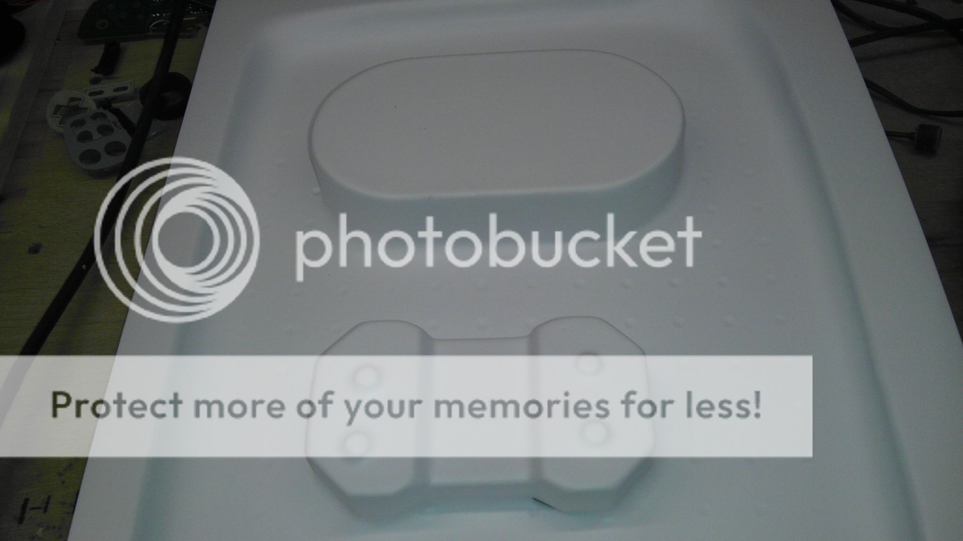
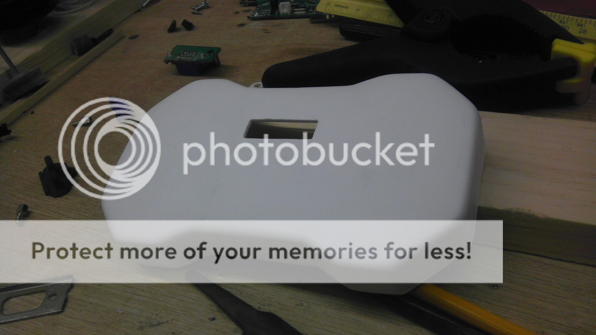
So I vac-formed the back half to an even 3/4" and started making the cuts for the N64 Memory pak and the output to the control ports on the systems. Now because of the change, I didn't need 25 wires, so I dropped down to a VGA cable with 15. I like this as well because I'll be able to simply unscrew the cable from the controller and control box when not in use.

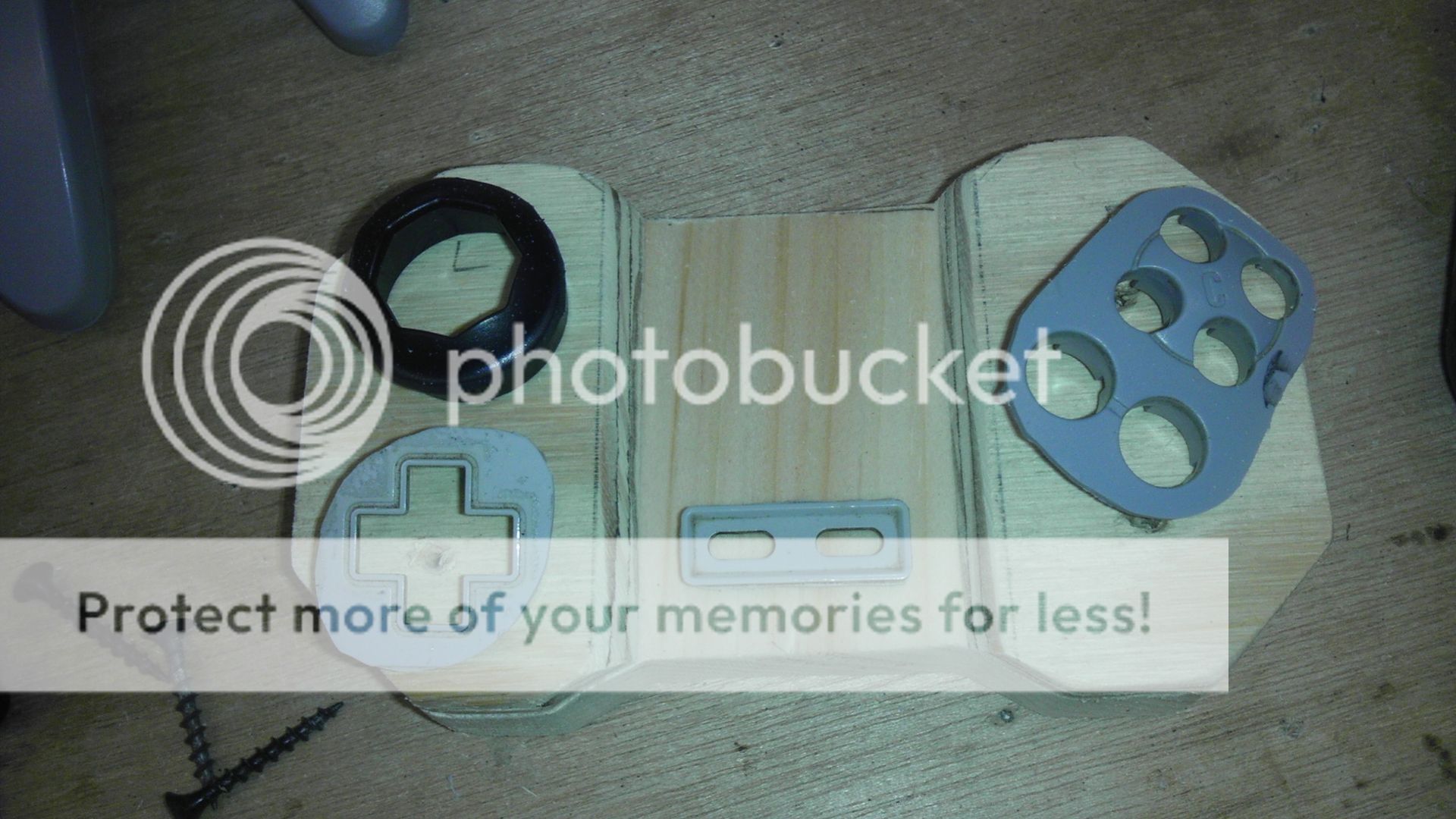
Here you can see the hole for the memory card.
IMAG0696.jpg


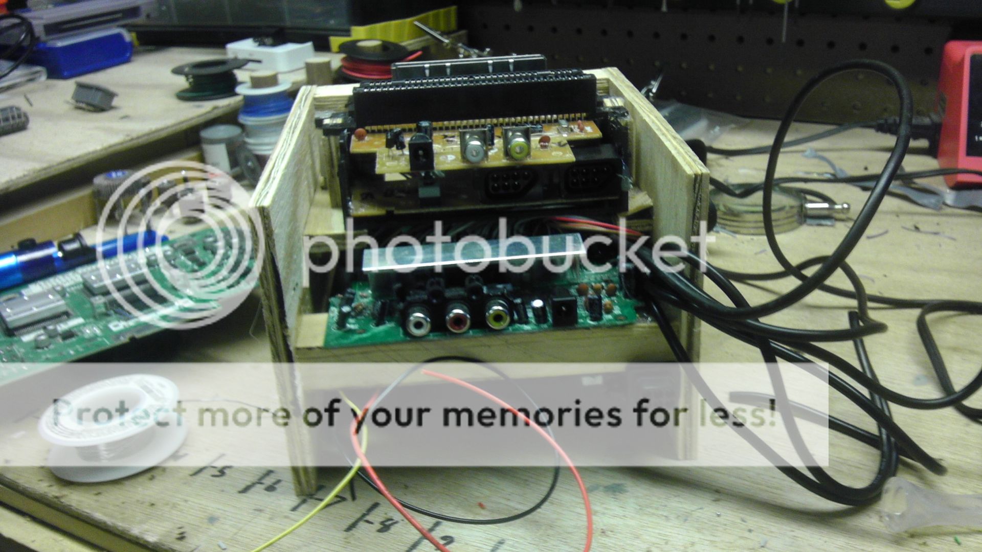
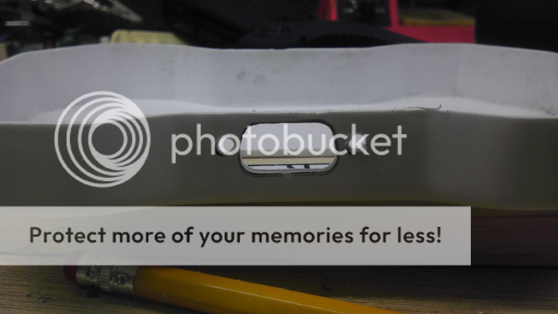
Here is the hole for the VGA Receptacle.
IMAG0697.jpg


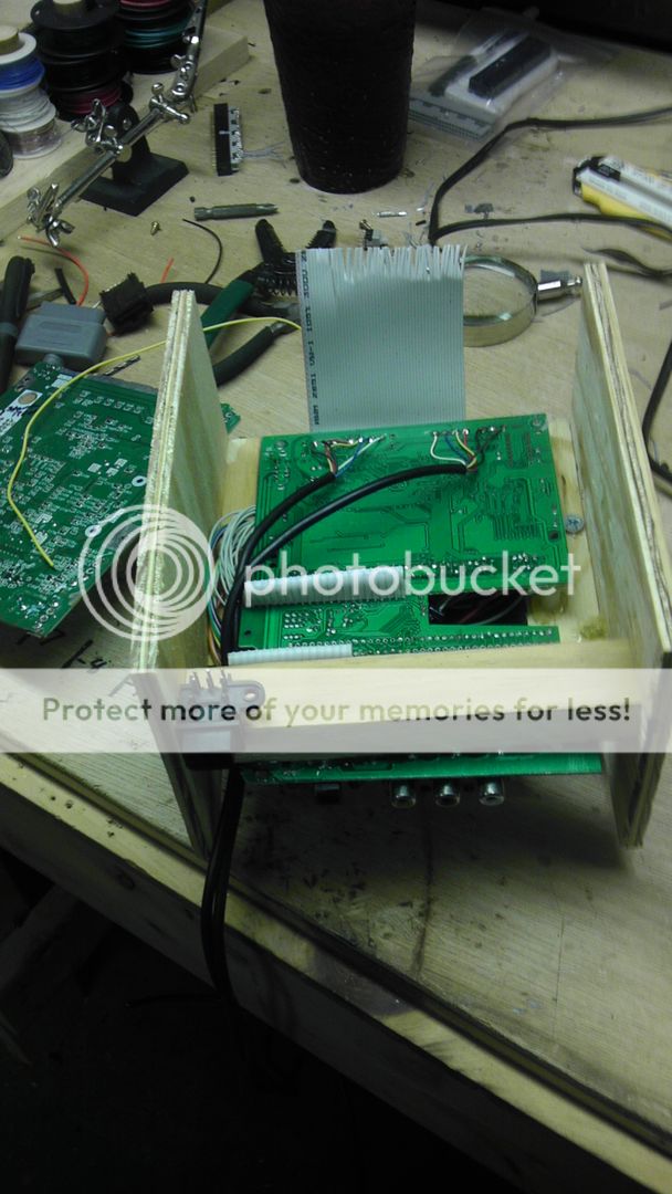
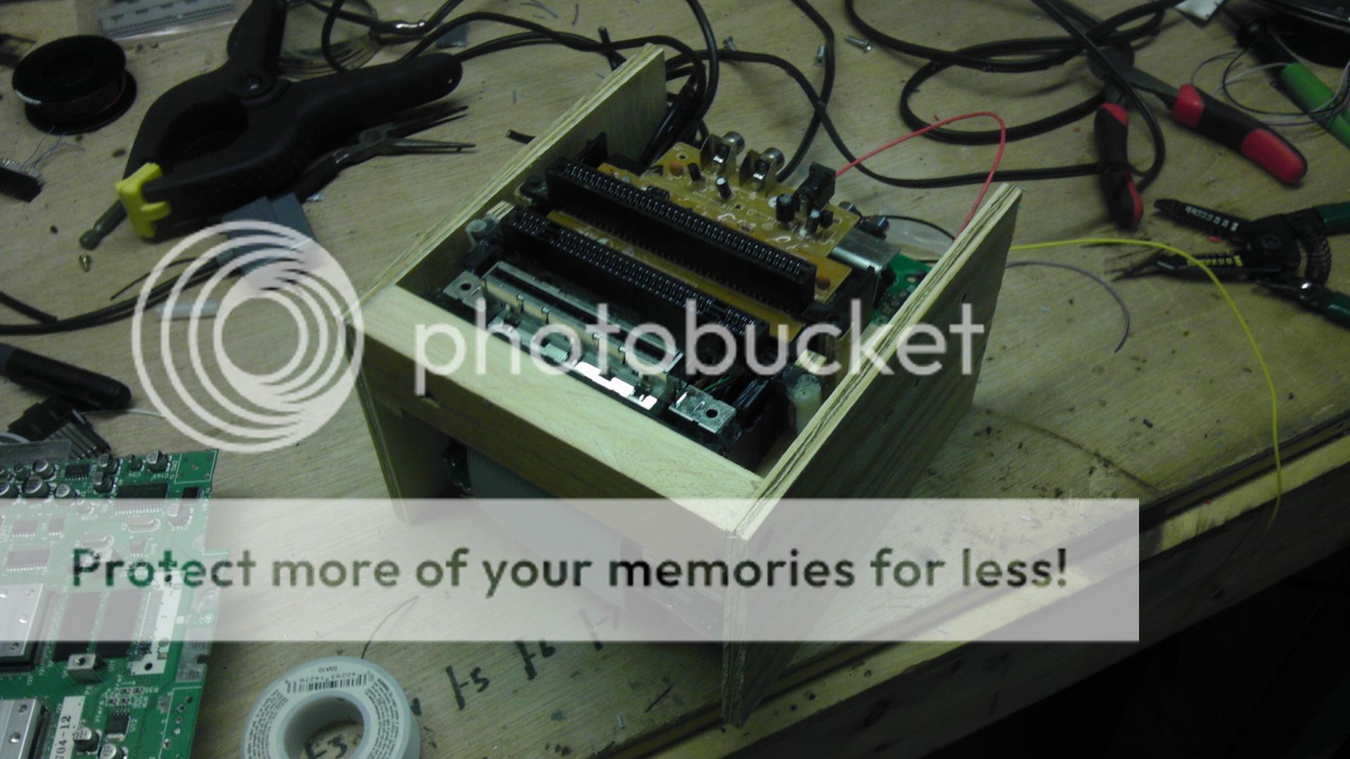
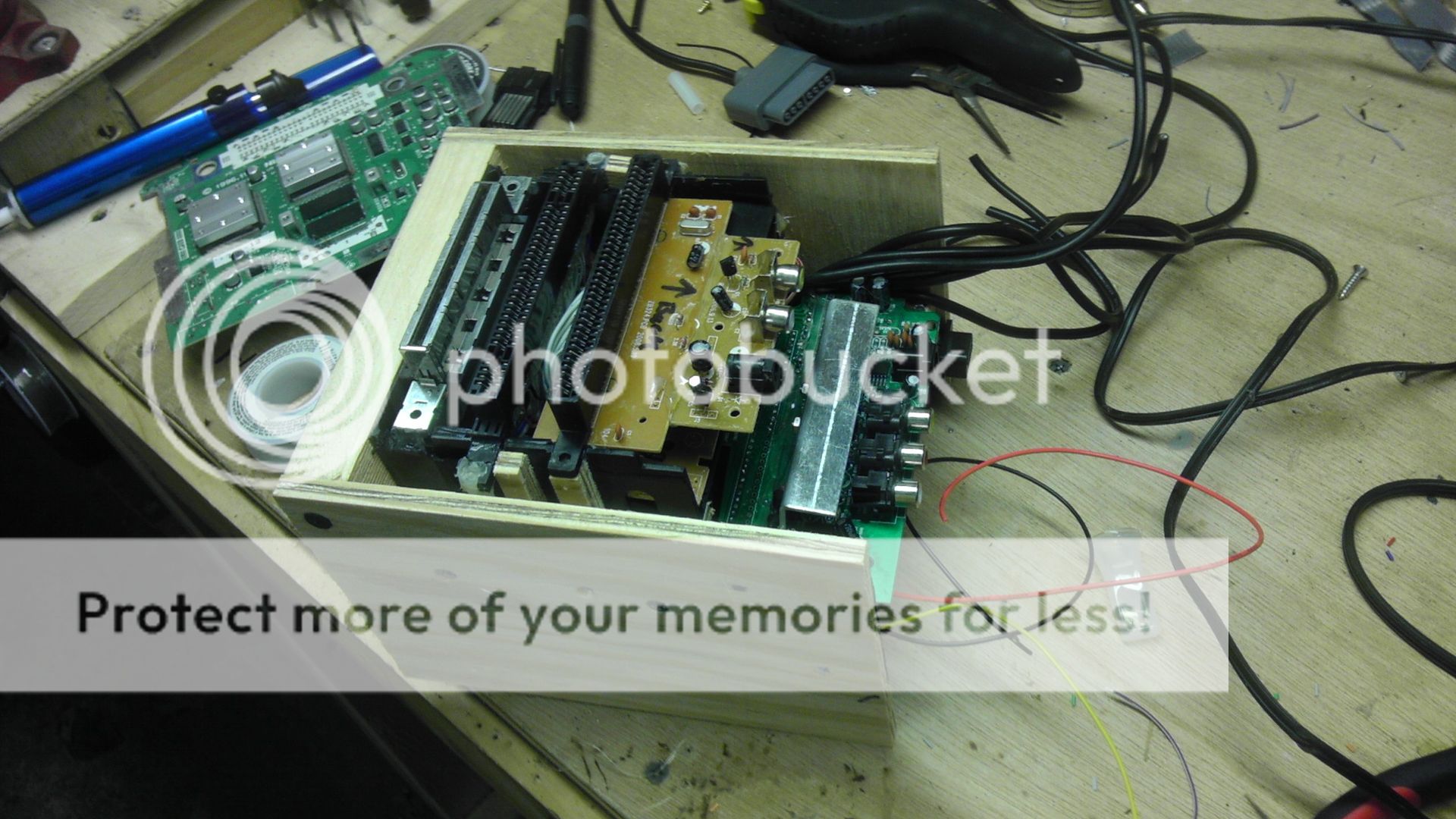
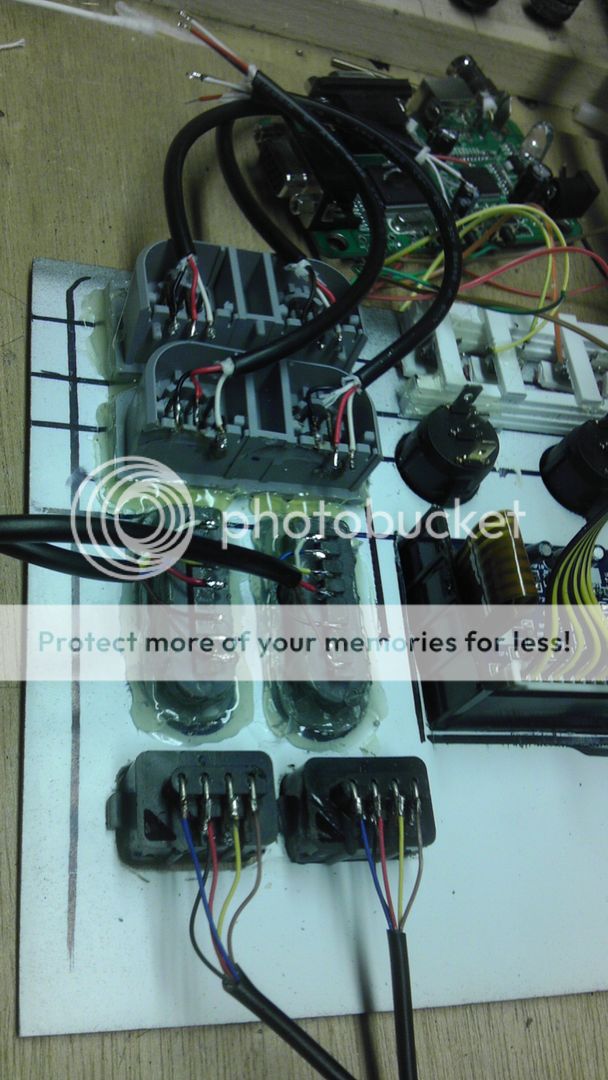
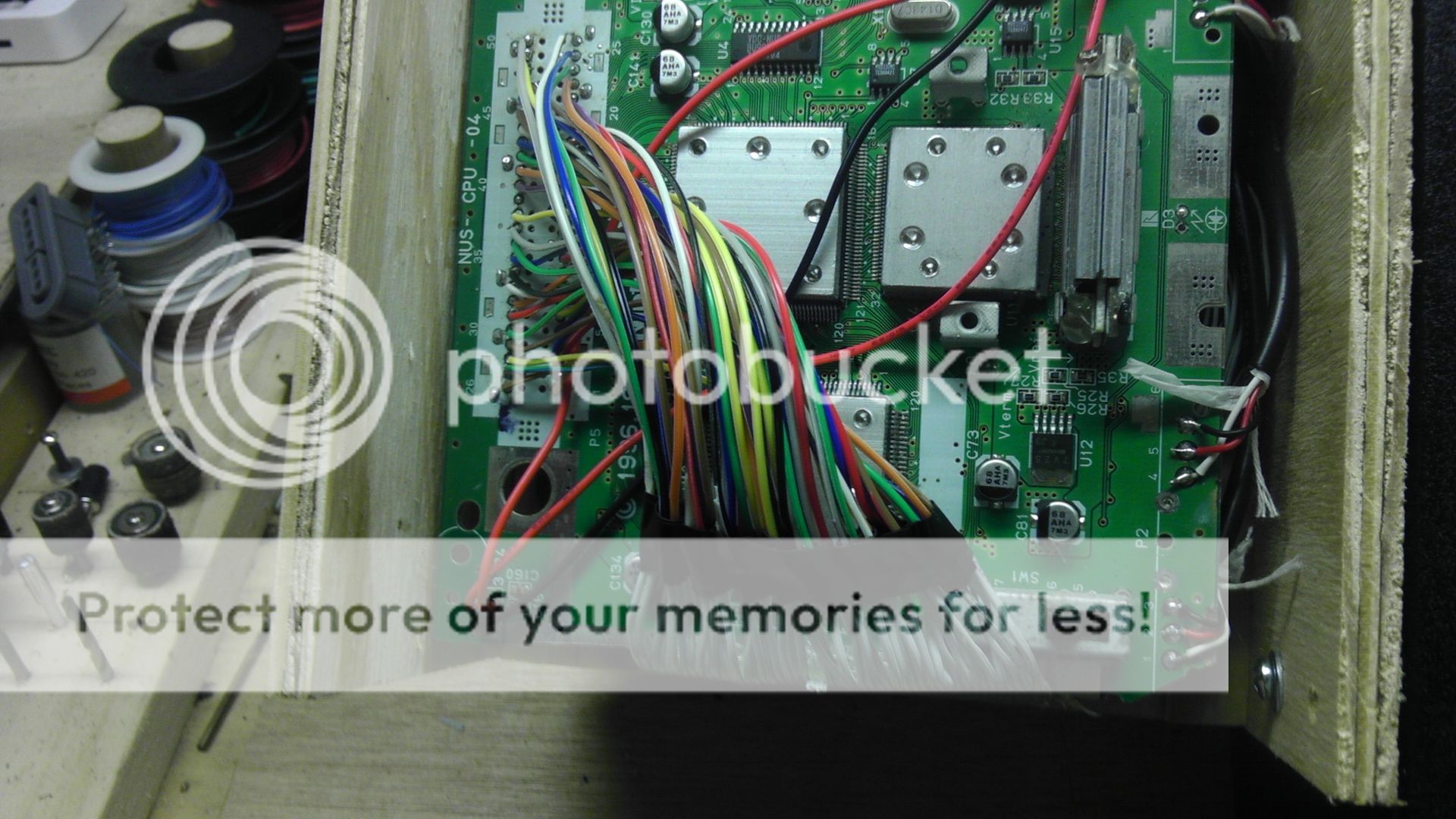
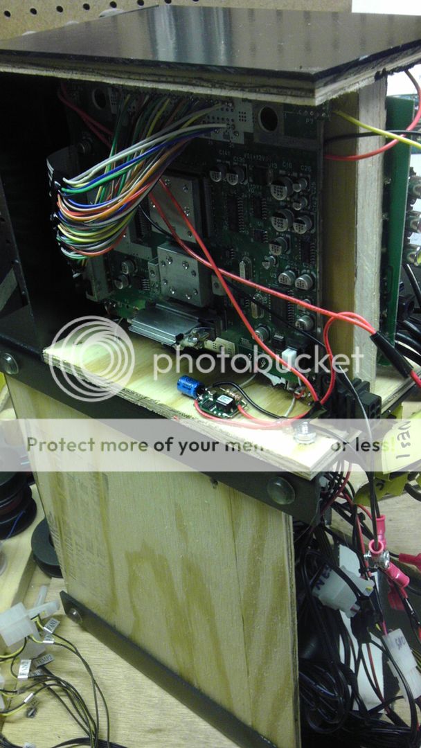
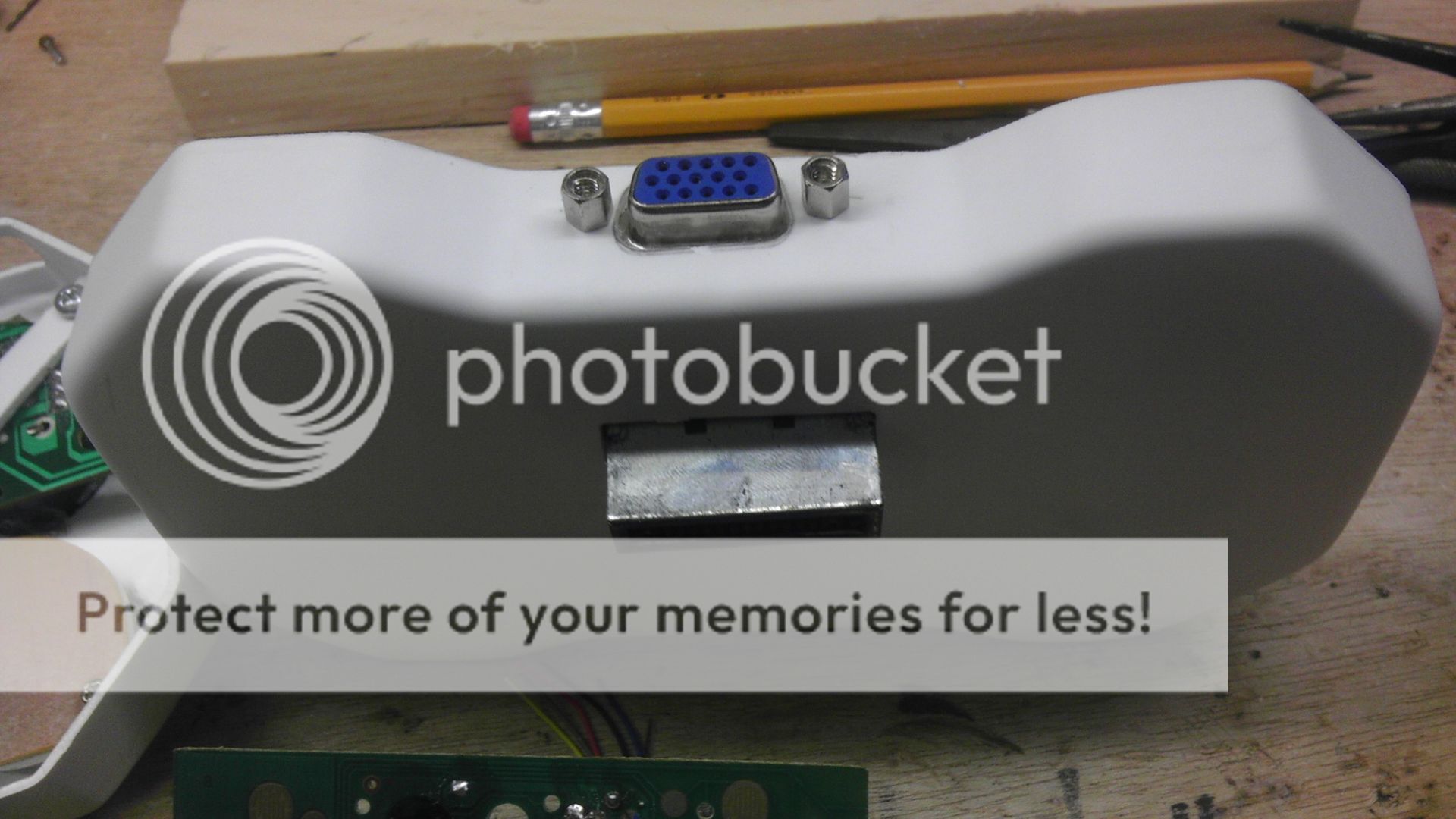
And here is the case with the N64 PCB and VGA receptacle mounted in place.
IMAG0699.jpg


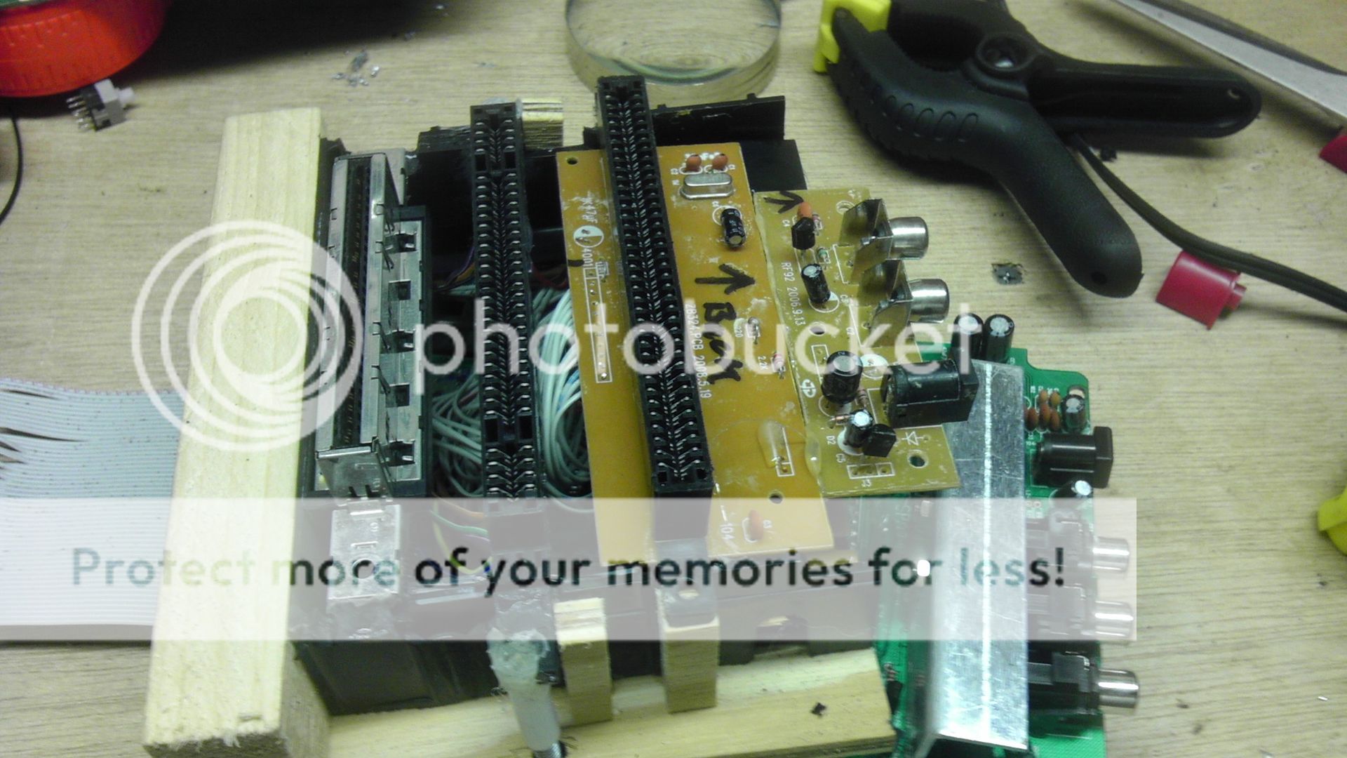
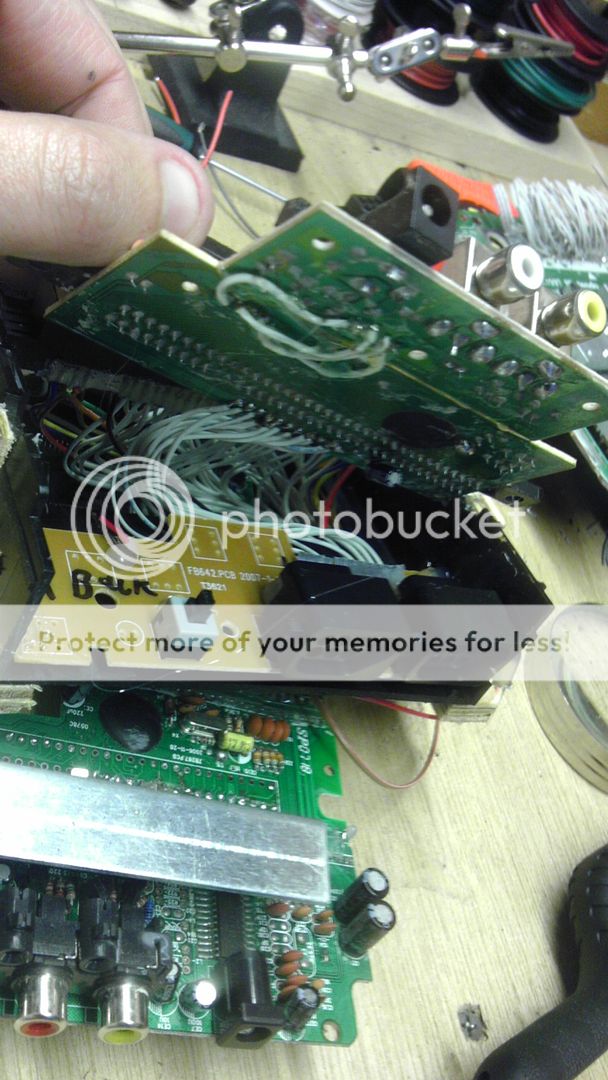
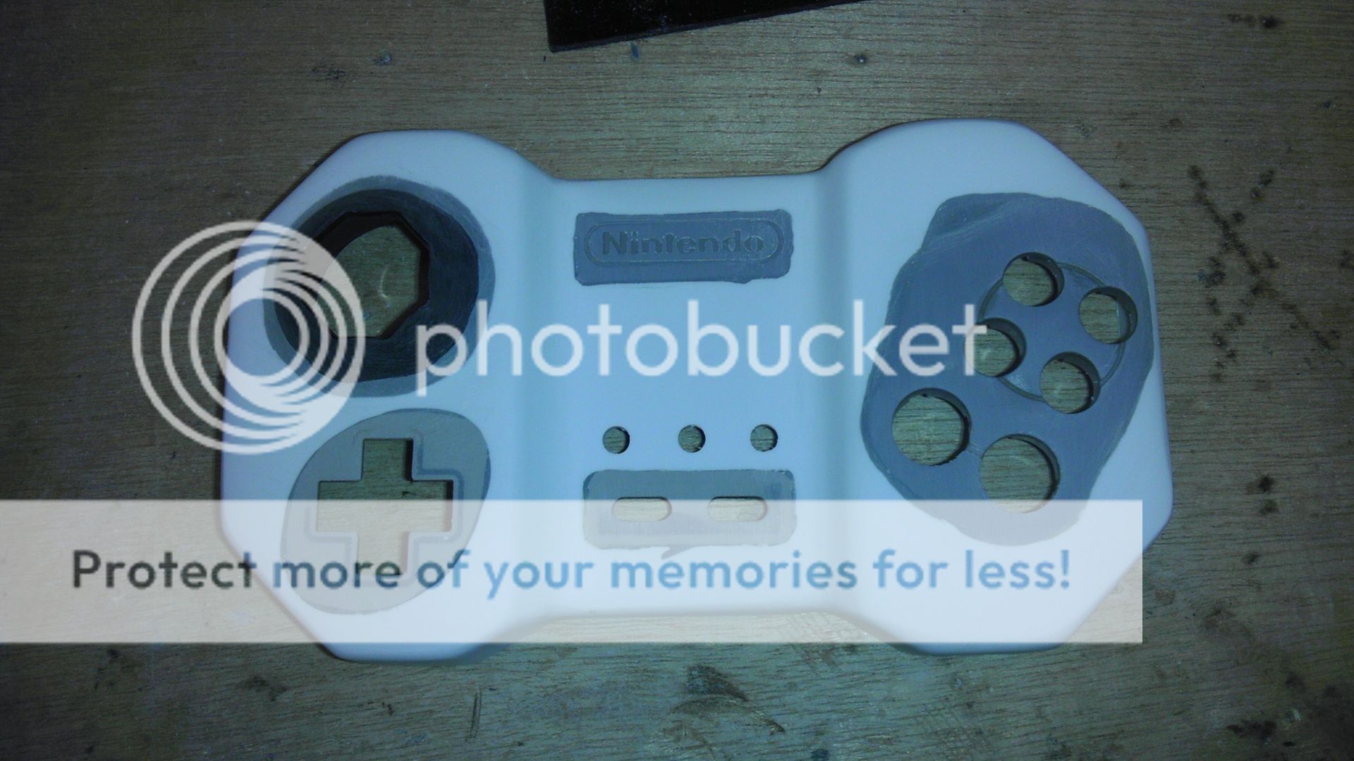
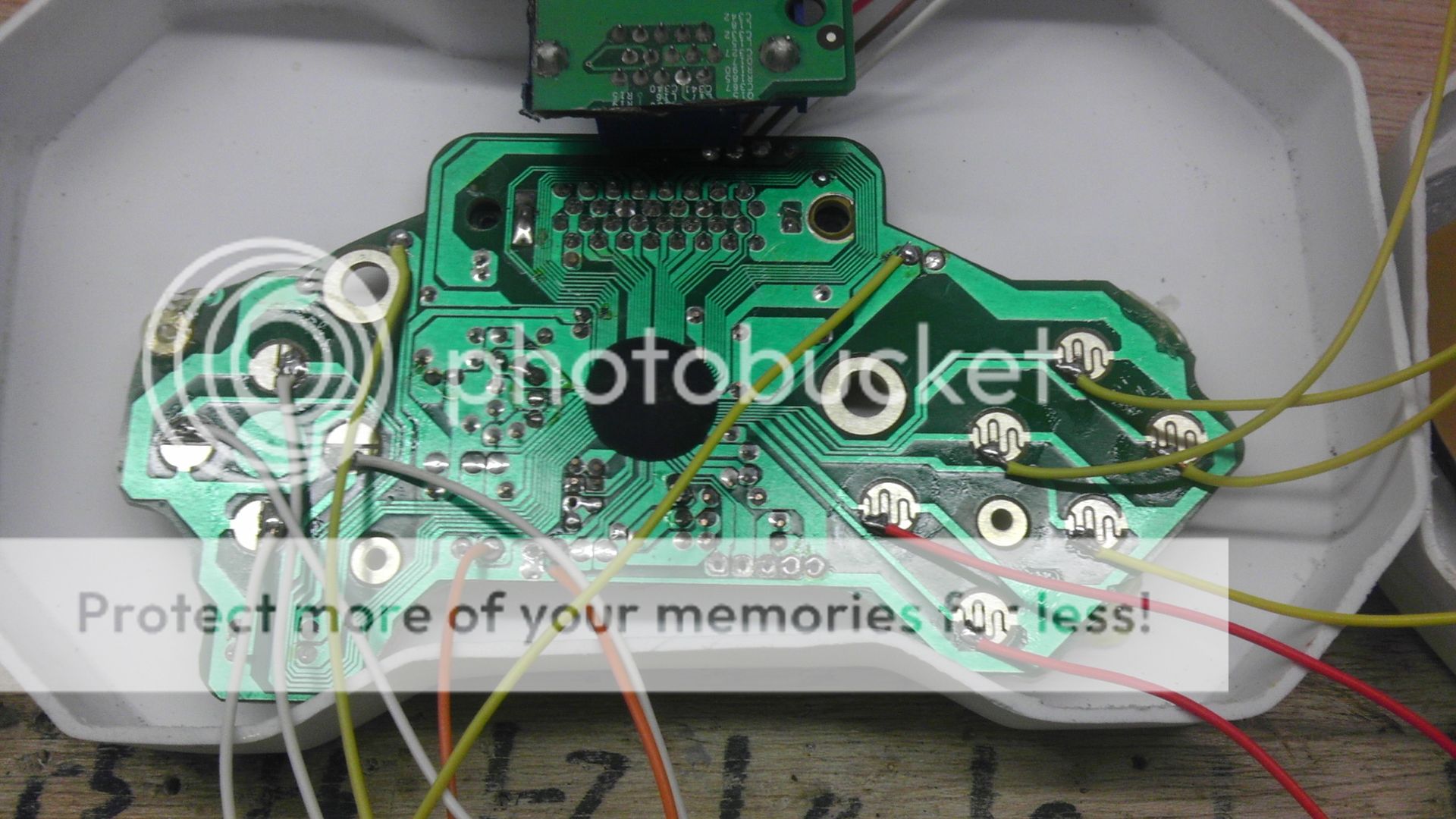
After they were mounted, I started wiring up the Super Pad controller. Strangely enough, this was my second Super Pad as I screwed up the first one, but when I opened up this one, I found that it was nearly a completely different layout than the first one which is located in the reference section. I was lucky I was able to make it fit as the traces below the D-Pad were very near the bottom of the controller and I had already cut the hole for the memory card slot and it just barely fit being trimmed down. I've got the room so I am trying to do as little reduction as possible because soldering to the big copper pads is much easier and more secure than soldering to just a trace. And this is the biggest board of them all so I should be good. I know how to make a SNES board super small though as well (from my SNEXBOX controller I did) so I shouldn't run out of room.
IMAG0700.jpg


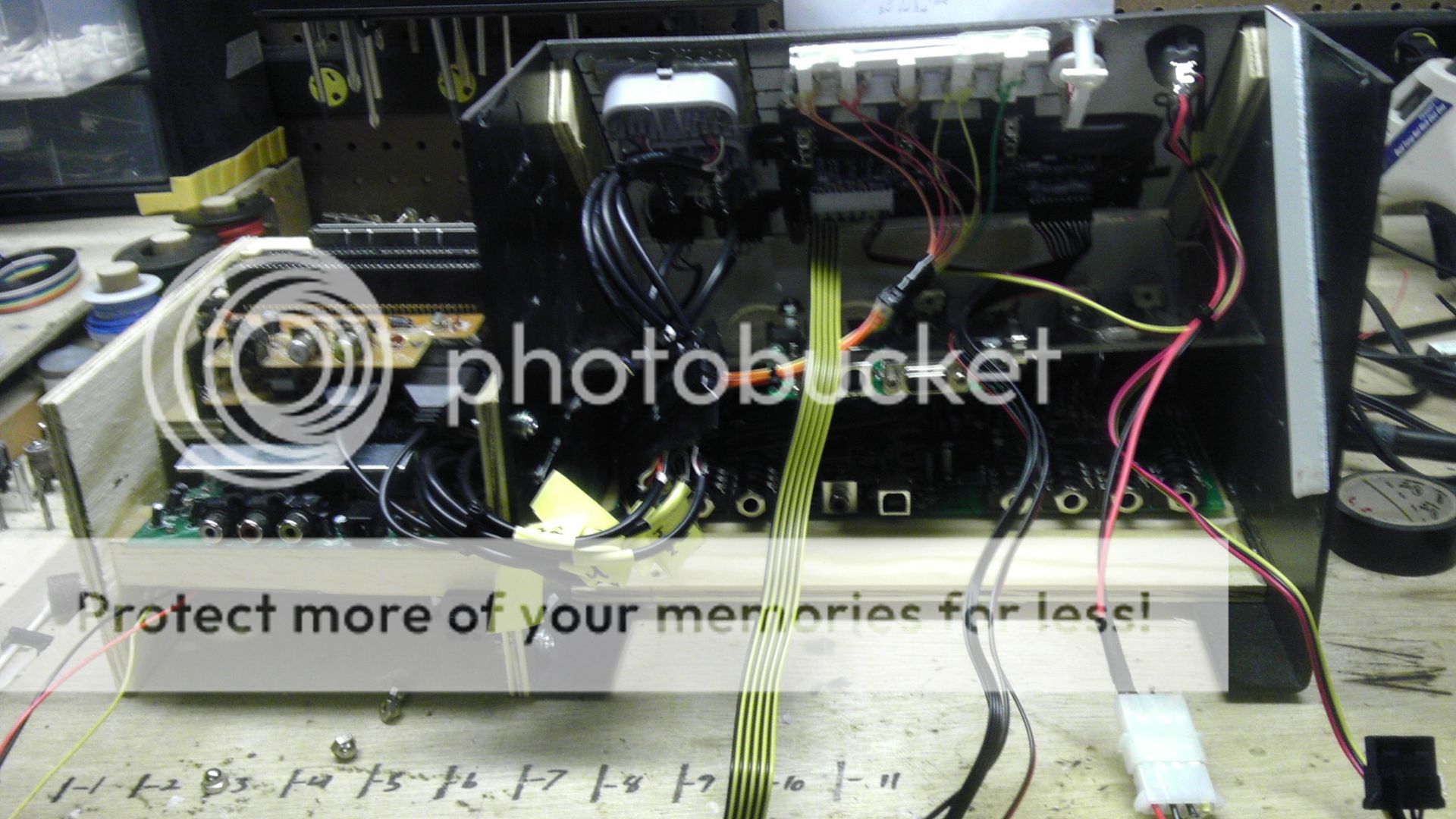
After I wired that up, I realized before I could do any testing of the connections I had to finish mounting all the buttons in the front half of the casing.
IMAG0701.jpg


First I mounted the shoulder buttons. I decided that L is going to double as the Z button on the N64 and I'll most likely be putting in a switch as with most N64 games, L is never used the same time that Z is just because of the way the original controller was laid out. This will be very simple and will save me a wire.
For the moment, the tact switches are just held in place by hot glue and pine. Though it's pretty strong, the one on the left will need to be reinforced a bit to make sure it doesn't bend over when pushed too hard. The long strip of pine in the middle holds both ends of the R & L buttons pinning them between it, so they are allowed to move up and down but not sided to side. Simple and effective.
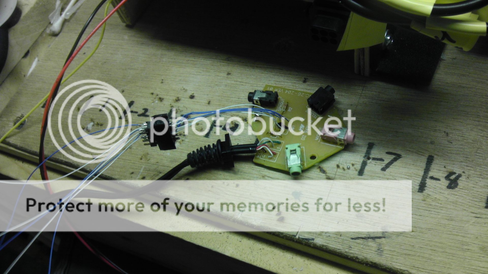
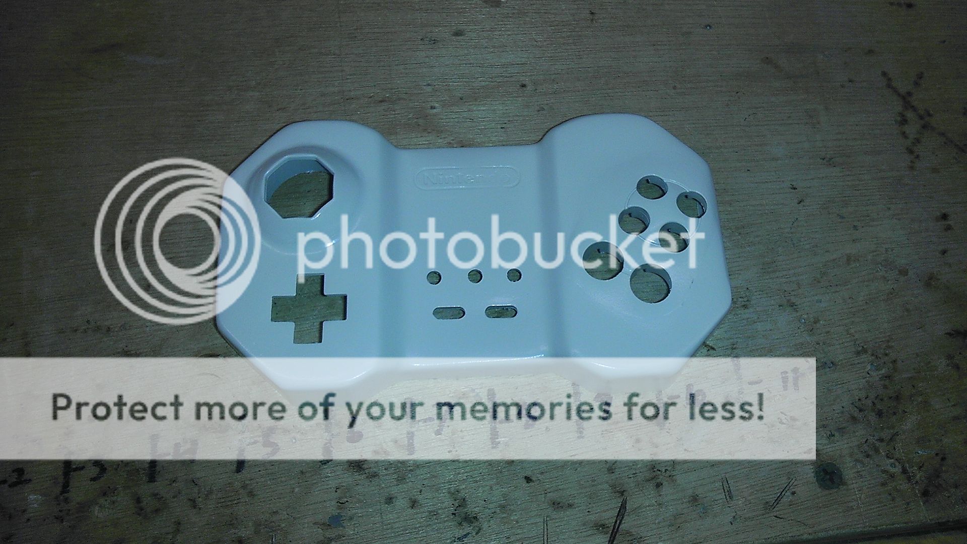
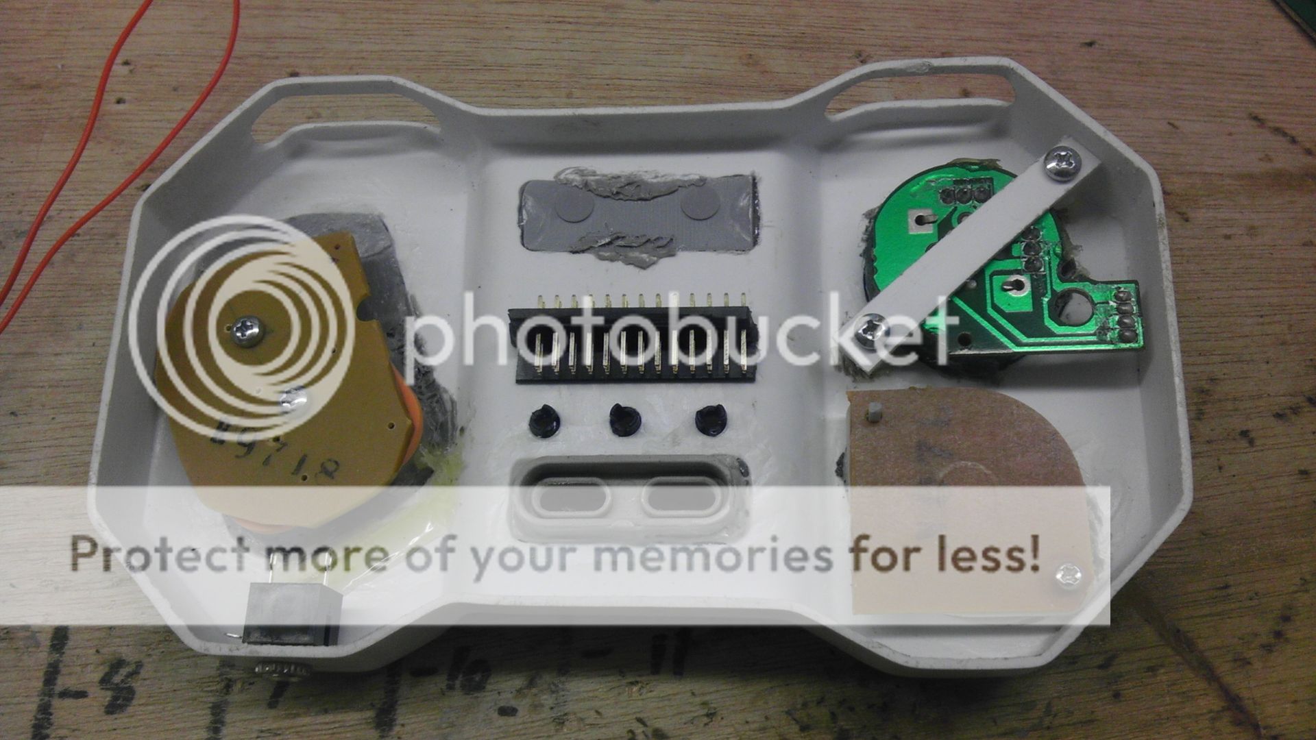
I next took two 4-40 Nylon hex standoffs and glued them on either side of the start and select buttons. I then took a piece of plastic styrene, drilled holes on either end to match up with the stand-offs and then glued two tact switches in place. I've really liked the idea of using screws to hold components in place because of the ability to adjust and remove with ease. They also hold much better than glues and seems to make the button presses feel more natural.
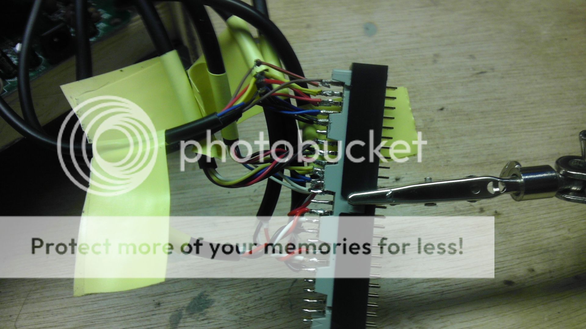
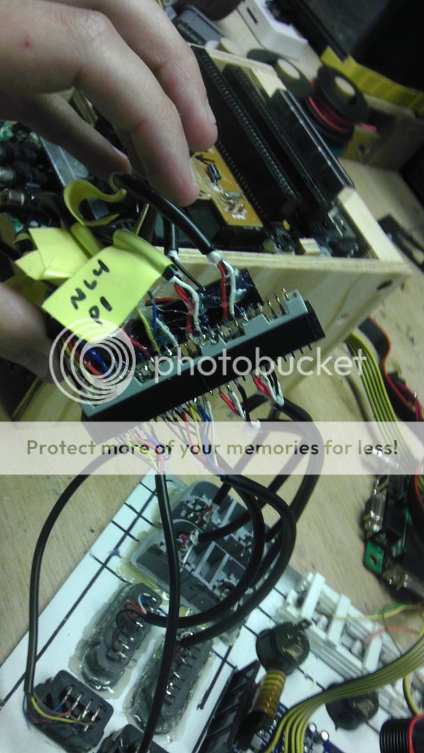
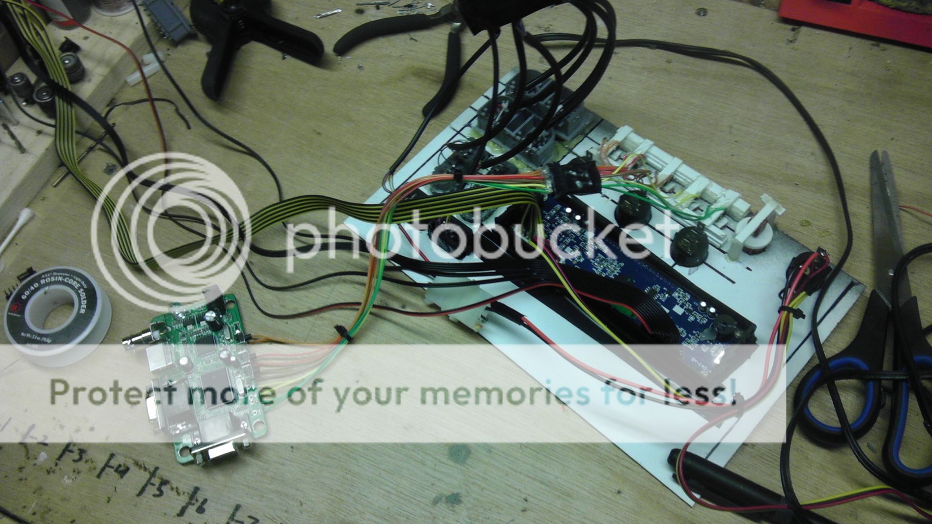
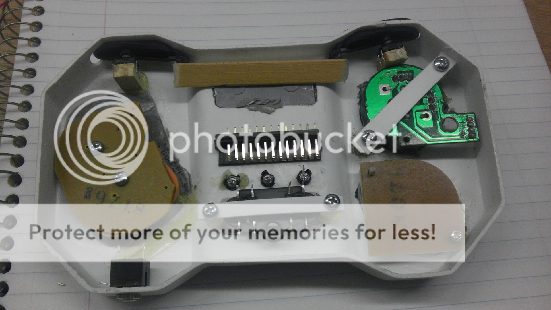
Next I took a 50 pin shrouded header, cut it in half, removed three sides of the shroud and super glued it to the deck. This is going to be the junction point for the buttons.
I then fit the three white LED's into their holders so now they are ready to have their resistors put in place and wired up when ready.
IMAG0702.jpg


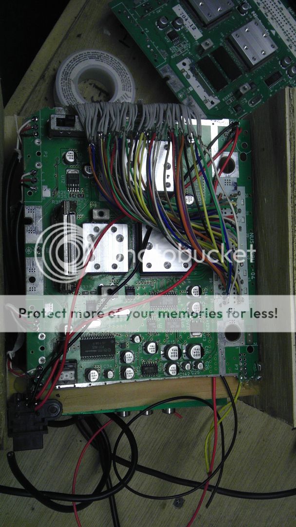
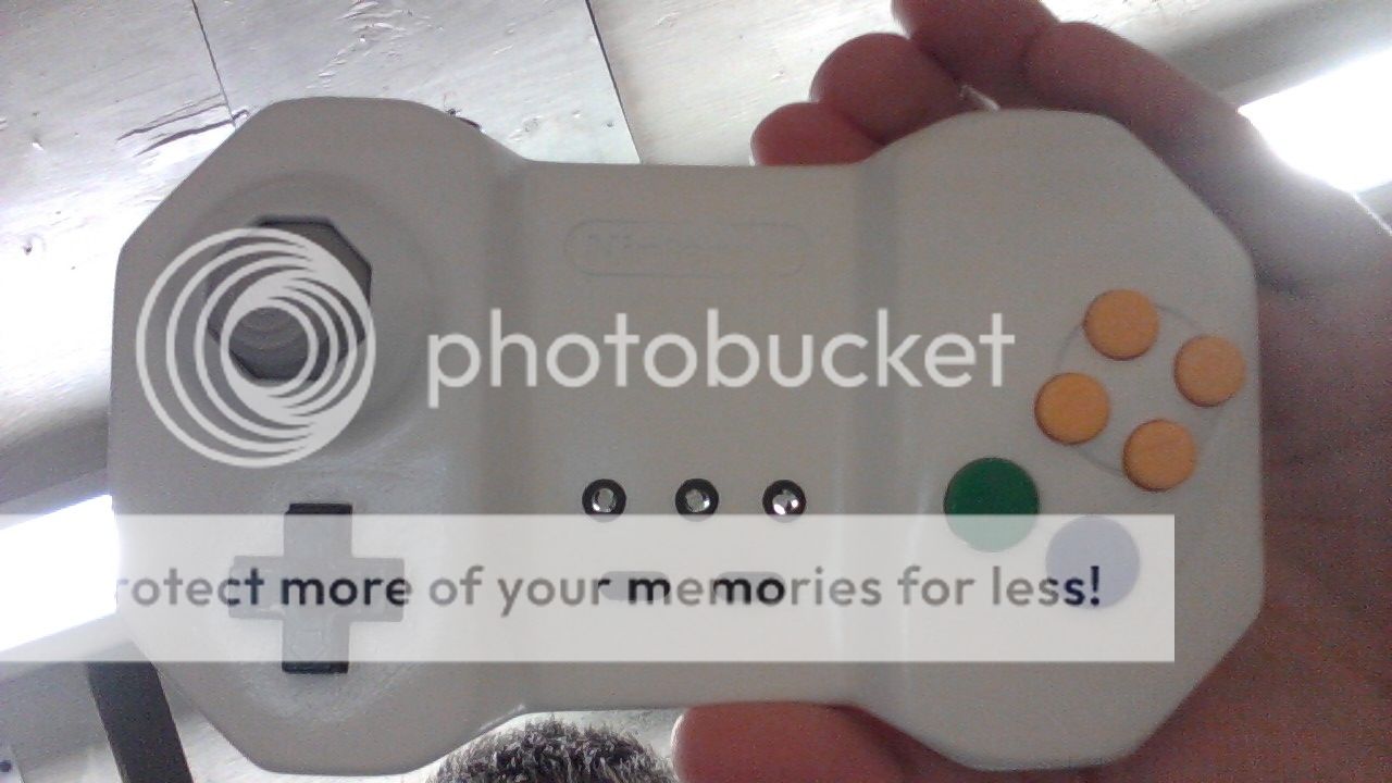
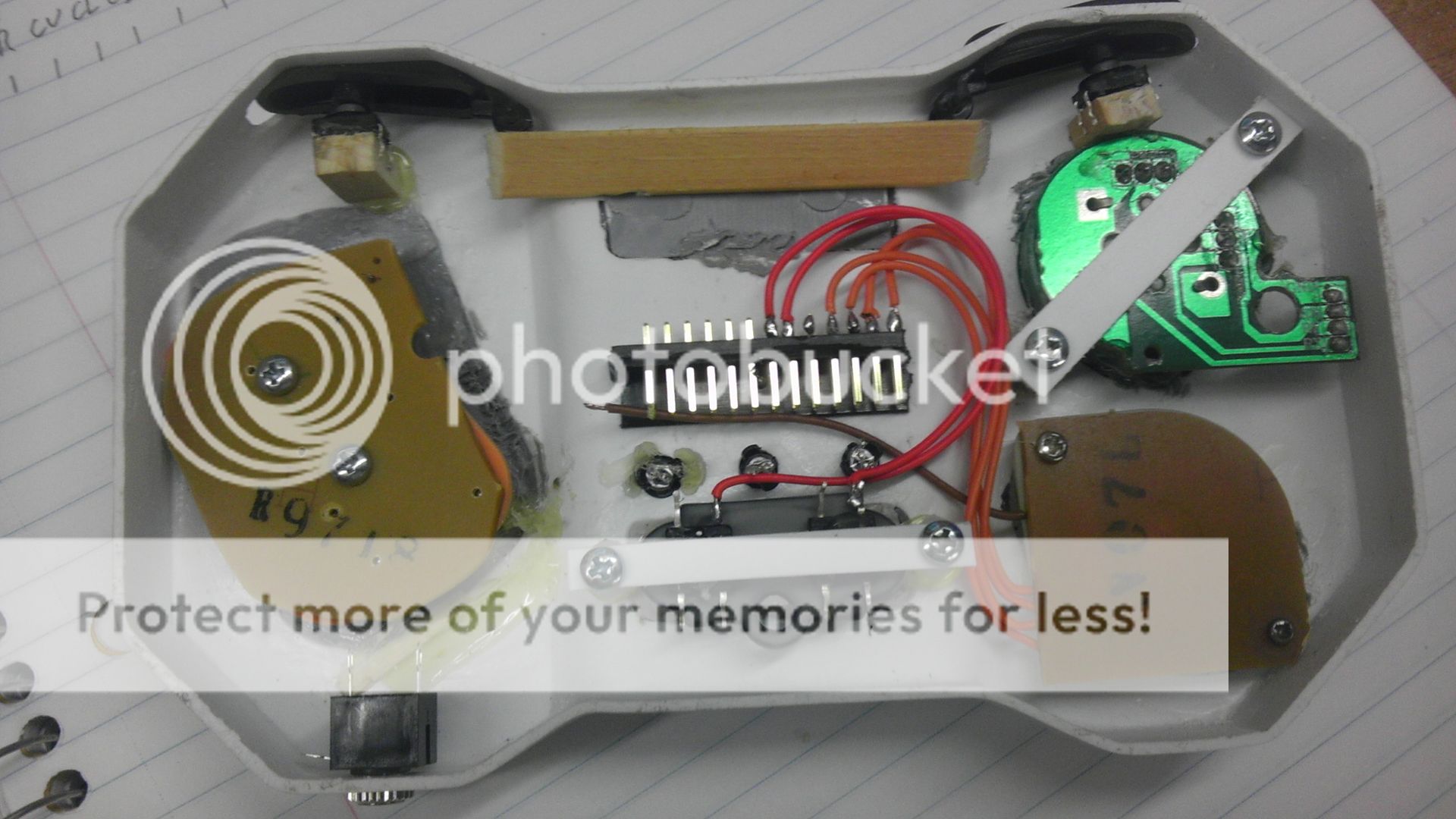
And finally where I finished off, I got the D-pad and the Start/Select buttons wired to their proper pin locations. You can probably see how this is going to work. On the top side of the header, the signal goes from the button to the header pin. As for the opposite side, most pins will have three wires converging on that one pin. So buttons A & B will have 3 wires each but C-up and C-R will only have one.
Like I said, I'm not sure I'll have to put master ground breaks depending on what system is in use at the time because they will all be sharing a common ground but that is a simple fix if need be.
IMAG0703.jpg


Phew...that was a long winded update, but it's been a lot of fun and this has been my last free week before my new job starts, as well as it being too hot to go outside for any length of time. Probably gonna get back too it in a bit, but I won't be broadcasting it as I'm pretty tired ATM.
 
Well thanks Nuke! I appreciate that :) I just like thinking outside the box really, even though everything I do in modding is all about making it fit into one. haha.

Final pic for the night, time to go watch a movie with the wife.

Everything except the control stick, LED's and Headphone jack are wire up. We'll get to the rest tomorrow.

IMAG0704.jpg
 
I love how you're making things using headers and plugs. It's quite proper and nice. I actually plan on making a few things using standard headers, molex connectors, etc.

I can't wait to see a finished project! It's looking quite amazing.
 
Back
Top