Downing
Well-Known Member
Hey guys! How have things been? Sorry to be such a stranger lately but things have been super busy over here for the past few months and posting/forum time has been quite limited. For the past 6 or 7 months now I've been working on a decent sized project and am probably about a month away from a working prototype that I can share with you all.
With that said though, today I decided that it was time to take a break from that for a couple days and work on a new project that I've wanted to do for awhile now that involves enhancing my CNC setup. In the interest of saving space in my shop, I decided to work on a way to combine my CNC's PC and control box into a more compact and better laid out unit.
The idea was to take out a lot of the dead space and bring everything together. So, I ripped apart both my CNC PC and the control box to the bare components. Did a bit of rearranging and mounted the primary pieces to a cut sheet of MDF. Never used MDF in a project before until recently and I have to say that I love the way it actually mills on my machine. Much more consistent than pine and I'll most likely be using this for my case molds from now on. Anyway, back to it.
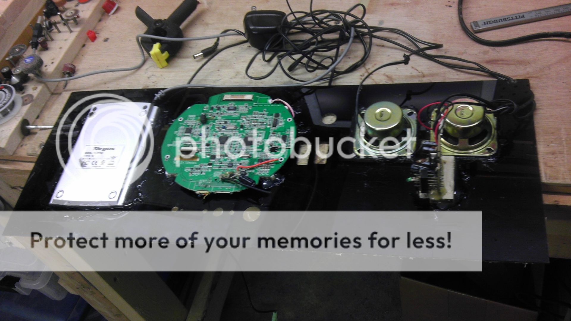
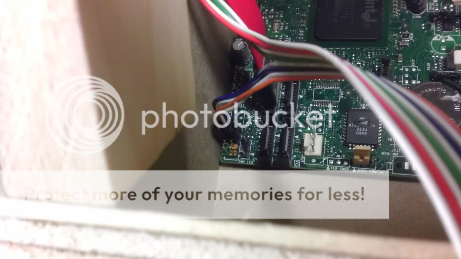
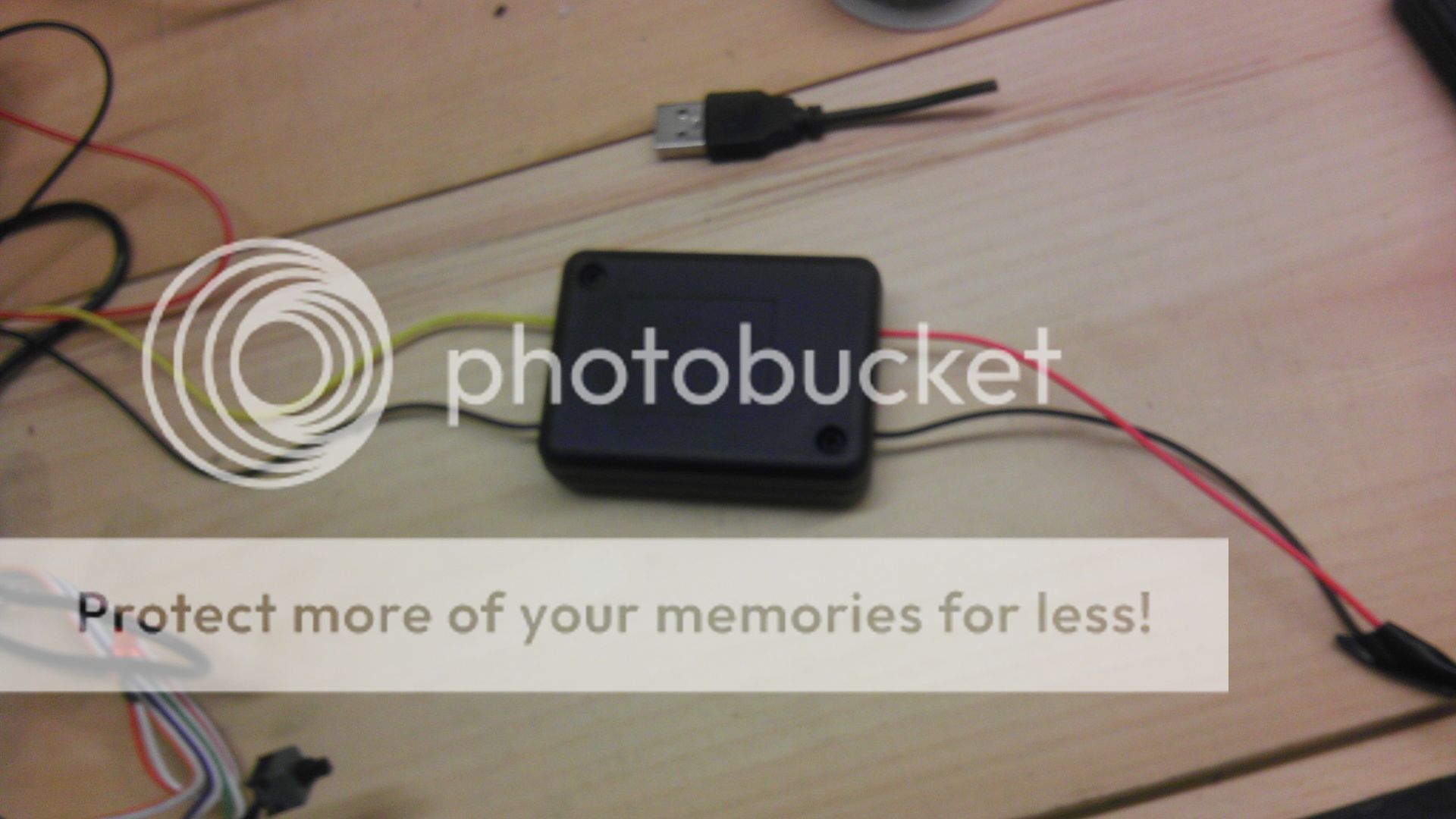
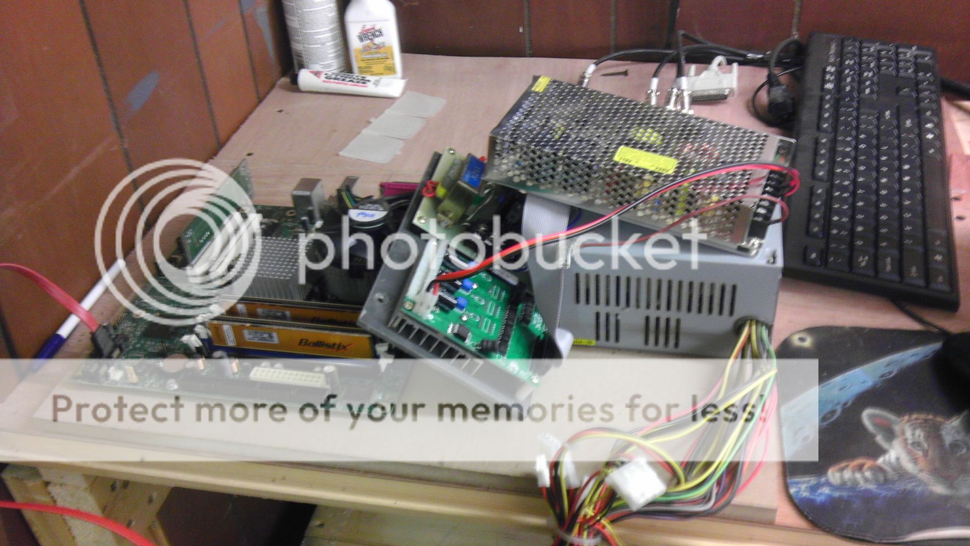
Here is a pic of the PC and the CNC control box in the nude.
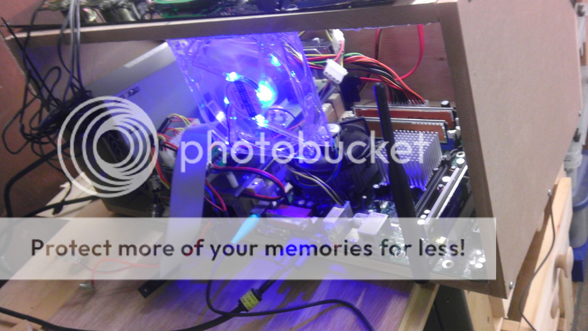
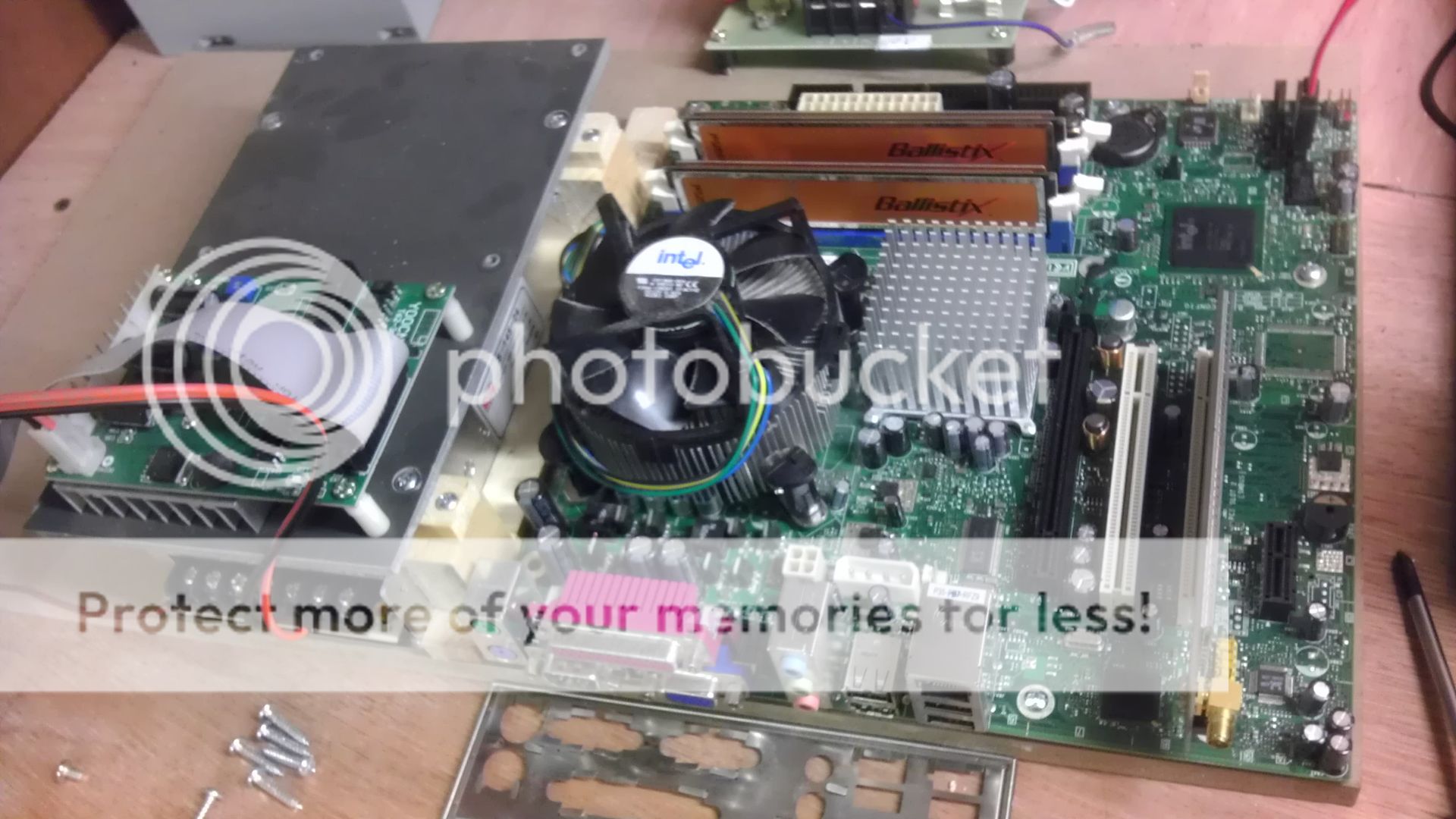
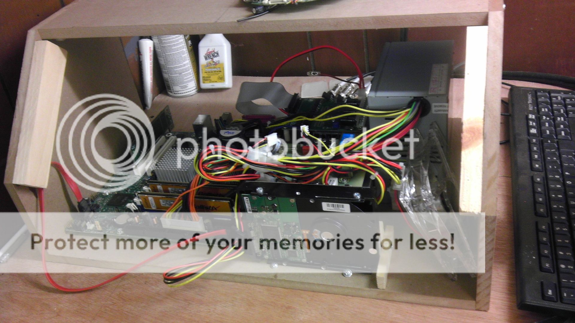
Here are the components a bit more organized, fastened down and stacked.
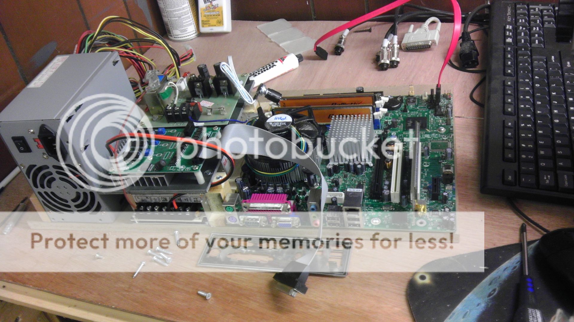
Same but with the power supply fastened in.
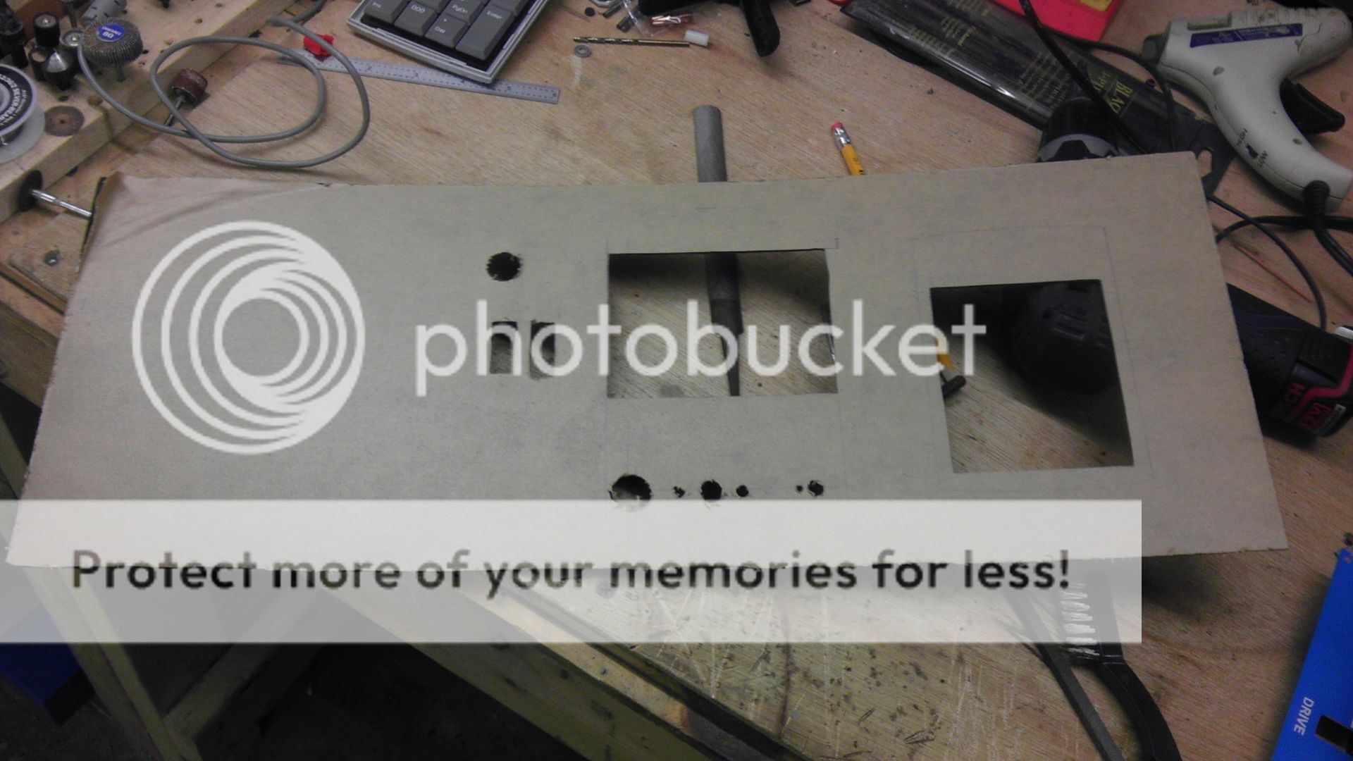
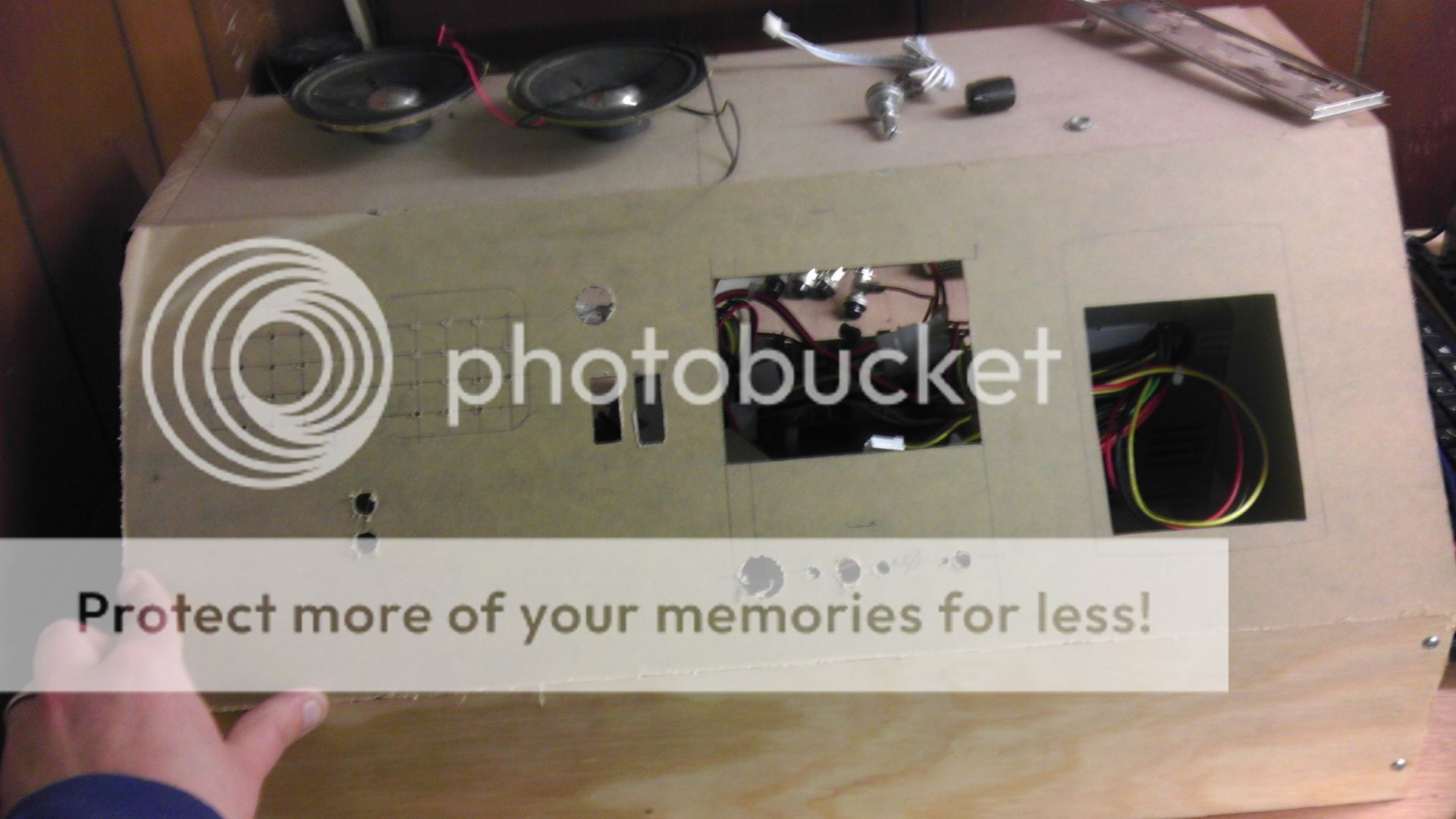
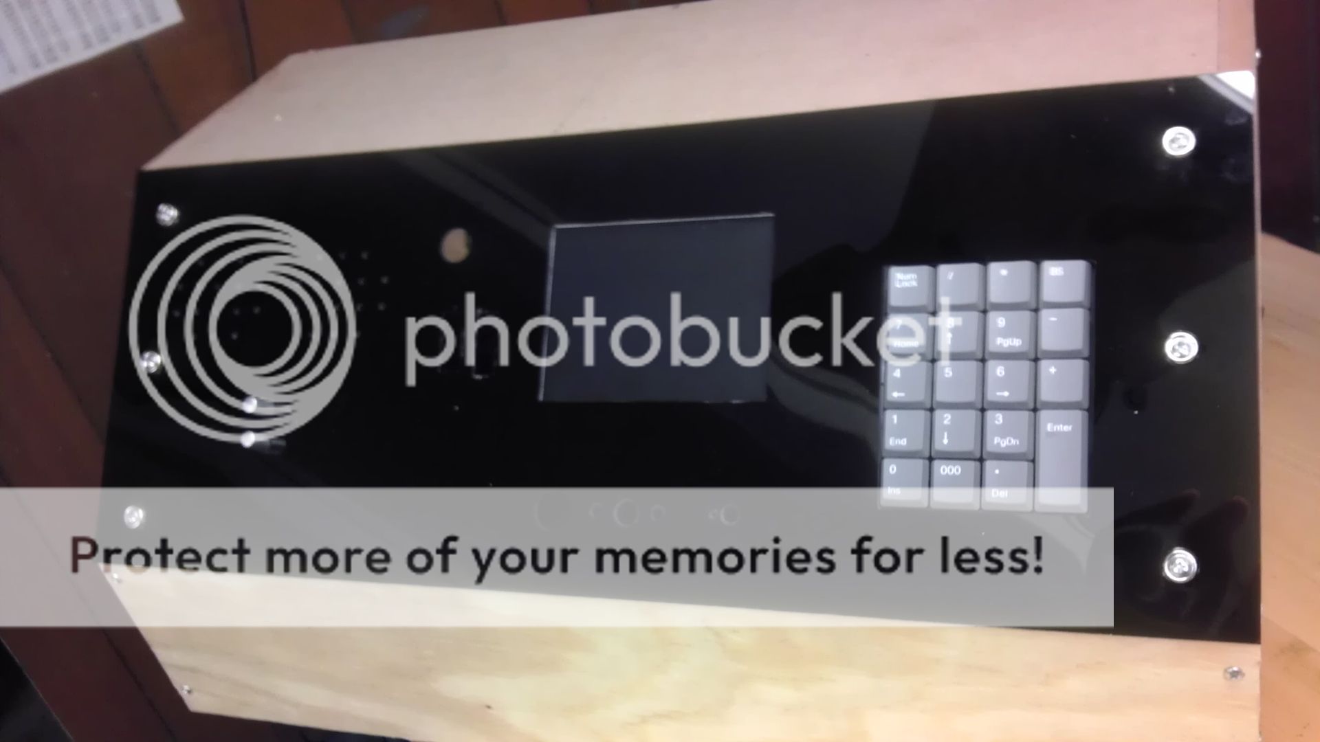
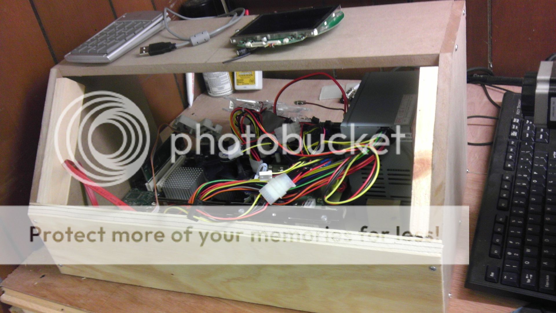
The sides and top cut and mounted as well as the hard drive.
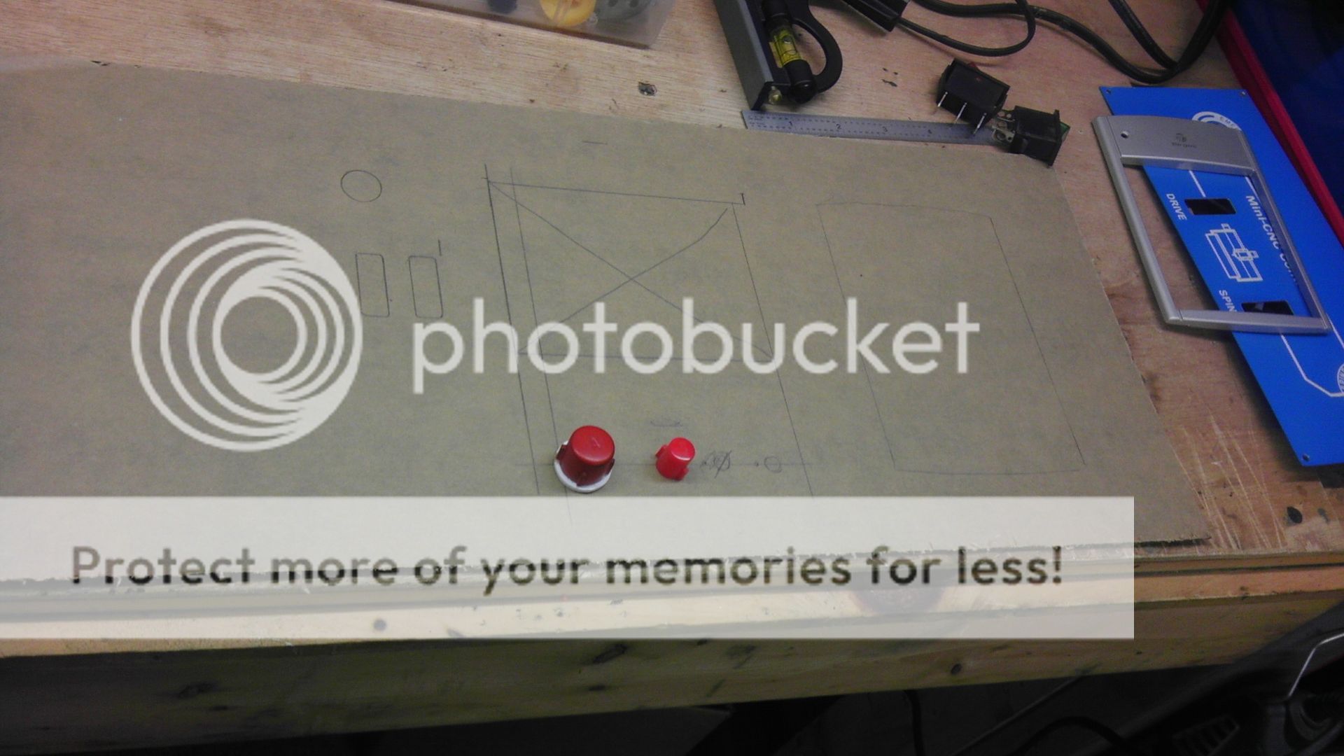
And now for the fun part...
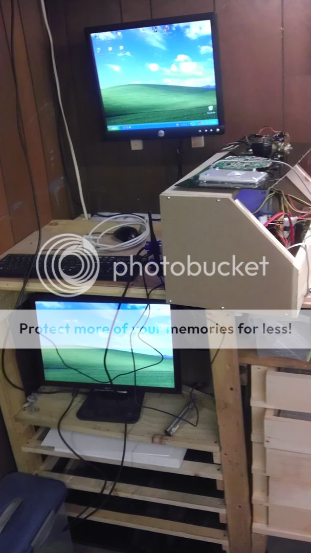
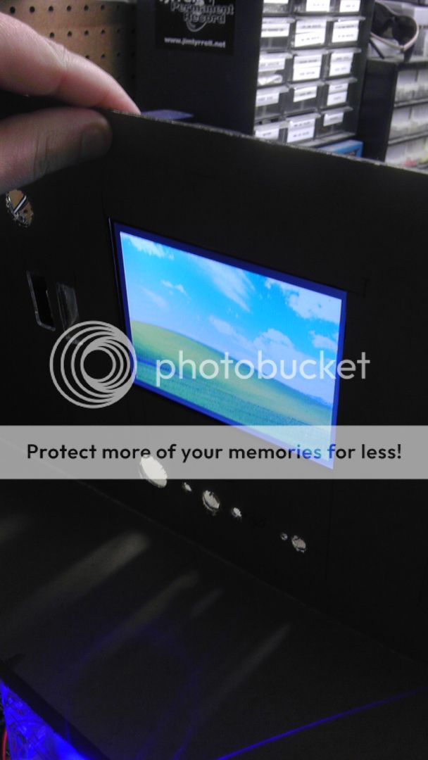
I'll be adding a graphics card that supports dual monitors and also have a VGA to Composite converter on the way which will allow me to run both my 15" flat panel and a 5" PS1 screen I had laying around built right into the dash of the unit. This will be useful to have with Mach3 running and just make the whole setup a bit more versatile. I'm also going to mount a USB numeric key pad to the right of the screen so I can make adjustments quickly as well as add a bit of convenience to the whole thing.
So far I've got about 3 hours into this and unfortunately until I get the basics sorted my CNC is down for a bit. But, it won't take long to get it running the way it was without the add-ons if the need arises. So hopefully Monday or Tuesday I'll have all the parts in to make this update work. More to follow shortly!
With that said though, today I decided that it was time to take a break from that for a couple days and work on a new project that I've wanted to do for awhile now that involves enhancing my CNC setup. In the interest of saving space in my shop, I decided to work on a way to combine my CNC's PC and control box into a more compact and better laid out unit.
The idea was to take out a lot of the dead space and bring everything together. So, I ripped apart both my CNC PC and the control box to the bare components. Did a bit of rearranging and mounted the primary pieces to a cut sheet of MDF. Never used MDF in a project before until recently and I have to say that I love the way it actually mills on my machine. Much more consistent than pine and I'll most likely be using this for my case molds from now on. Anyway, back to it.
Here is a pic of the PC and the CNC control box in the nude.
Here are the components a bit more organized, fastened down and stacked.
Same but with the power supply fastened in.
The sides and top cut and mounted as well as the hard drive.
And now for the fun part...
I'll be adding a graphics card that supports dual monitors and also have a VGA to Composite converter on the way which will allow me to run both my 15" flat panel and a 5" PS1 screen I had laying around built right into the dash of the unit. This will be useful to have with Mach3 running and just make the whole setup a bit more versatile. I'm also going to mount a USB numeric key pad to the right of the screen so I can make adjustments quickly as well as add a bit of convenience to the whole thing.
So far I've got about 3 hours into this and unfortunately until I get the basics sorted my CNC is down for a bit. But, it won't take long to get it running the way it was without the add-ons if the need arises. So hopefully Monday or Tuesday I'll have all the parts in to make this update work. More to follow shortly!