Crimson Cube v3 (For Commission)

RedmagnusX

Active Member
Hey Everyone,

I figured it was about time that I made a proper work log for one of my portable Cubes. This one was commissioned by Portable-Junkie here on the forums. I figured a work log would be a good way to keep him in the know as to how I'm progressing as well as to be a potential source of knowledge for those who may be just starting out who want to tackle the Gamecube themselves.

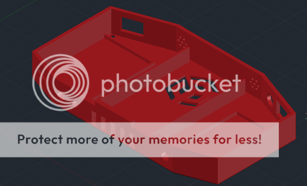
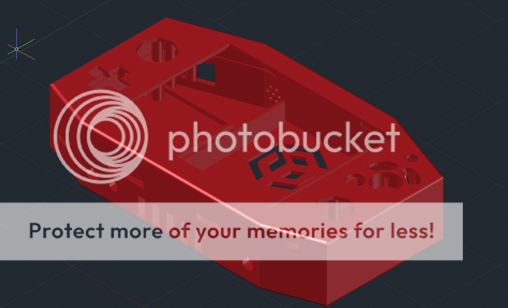
This portable will share the design of the Crimson Cube v2, effectively making it the Crimson Cube v3. Here's some 3d renders of the design from AutoCad.


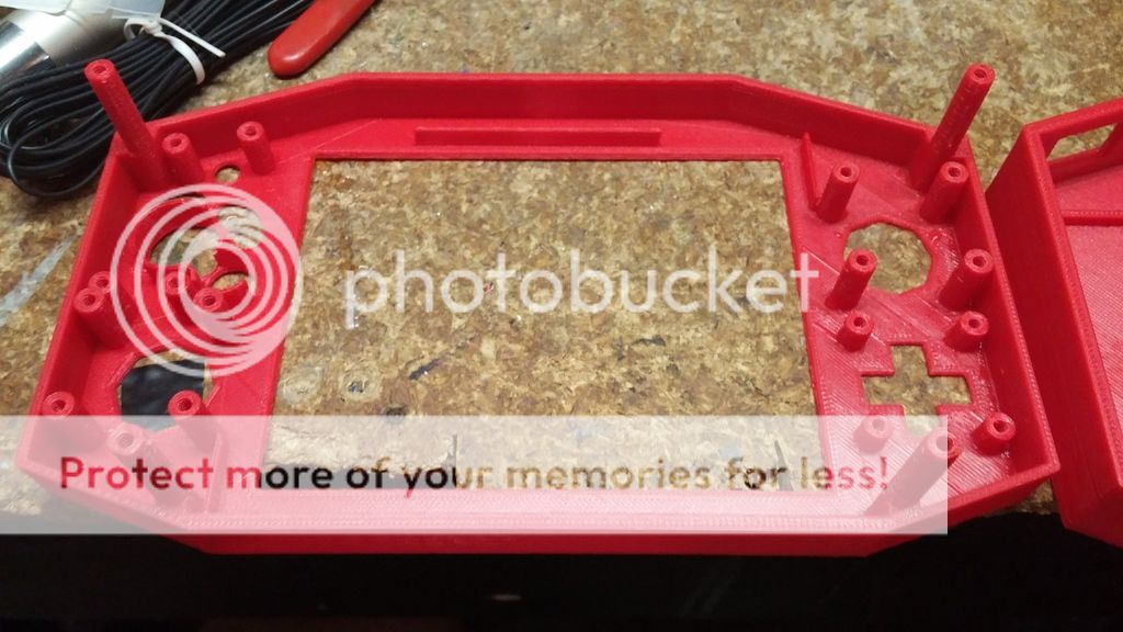
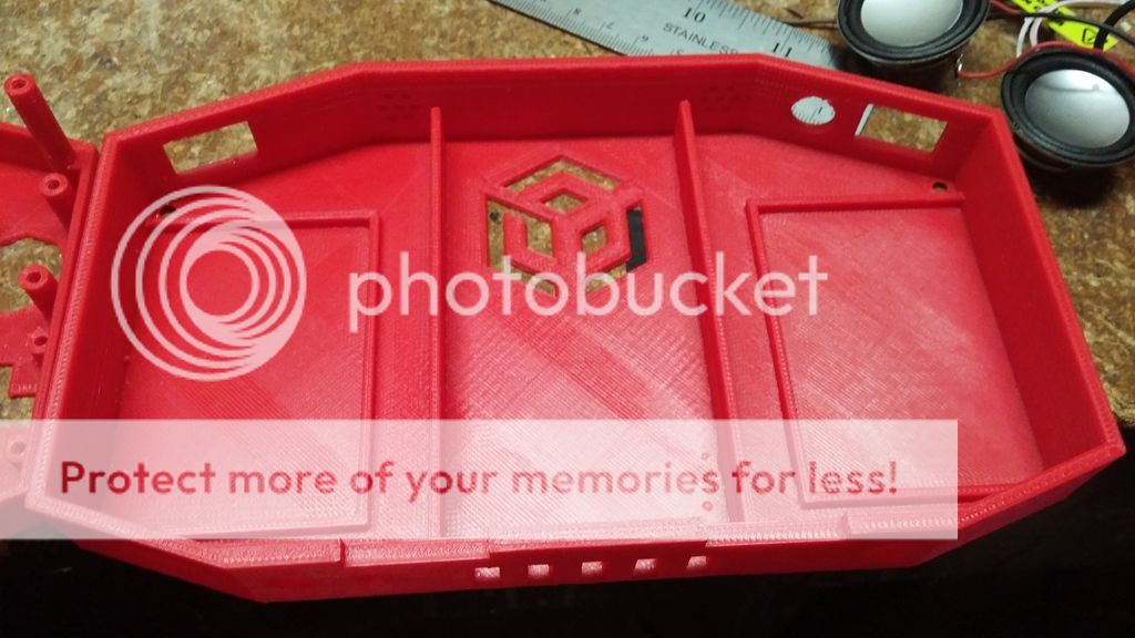
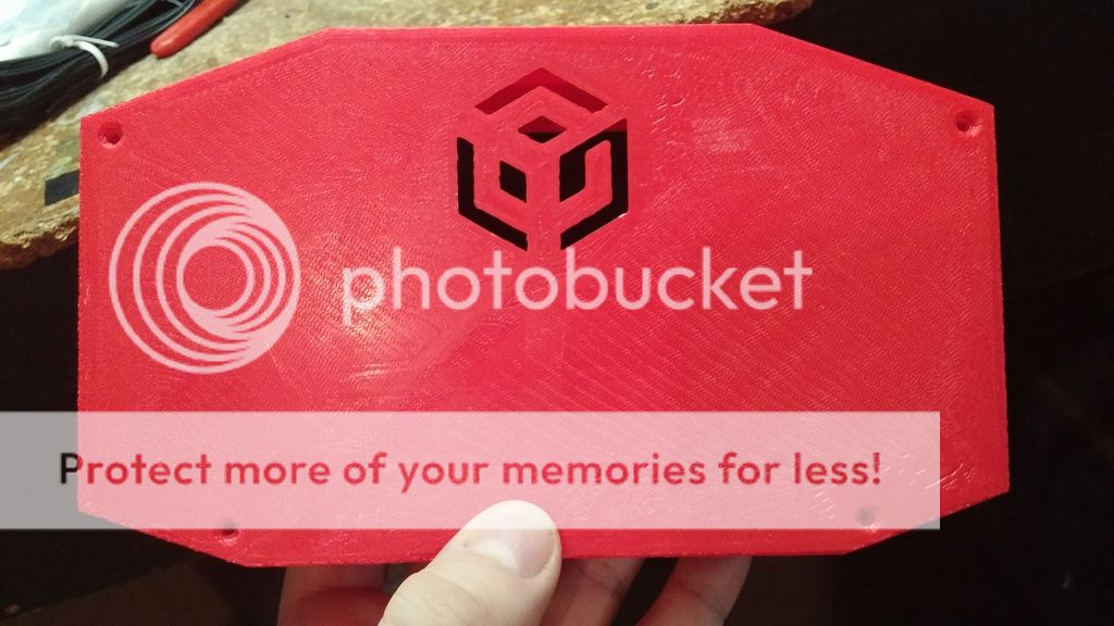
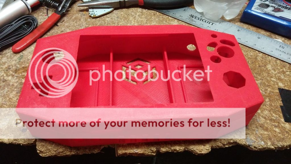
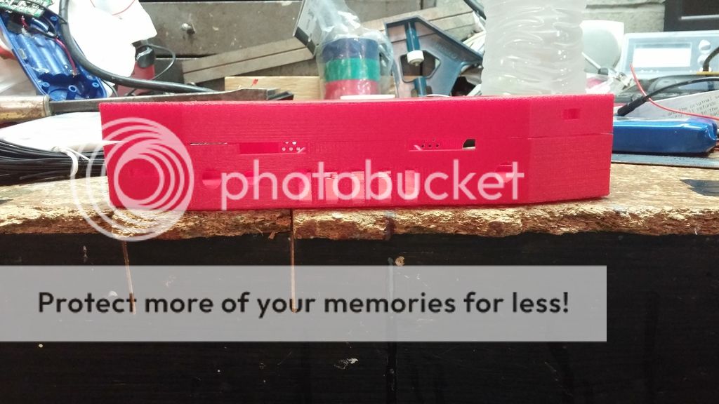
My next step was to print out the design via 3d printer. The pictures below are of the case fresh off the printer.


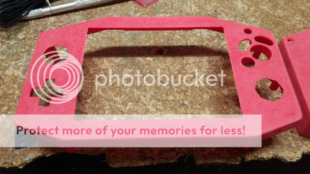
After showing the pictures of the raw printout to my client, he questioned the color of the shell. In order to make sure he was happy with the result, I opted to paint it a deeper shade of Red. So the pictures below are of the shell after the prep and paint process.

Sanded and Ready for paint:


Painted:


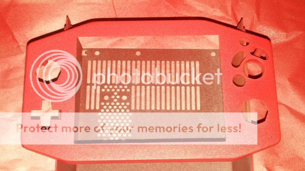
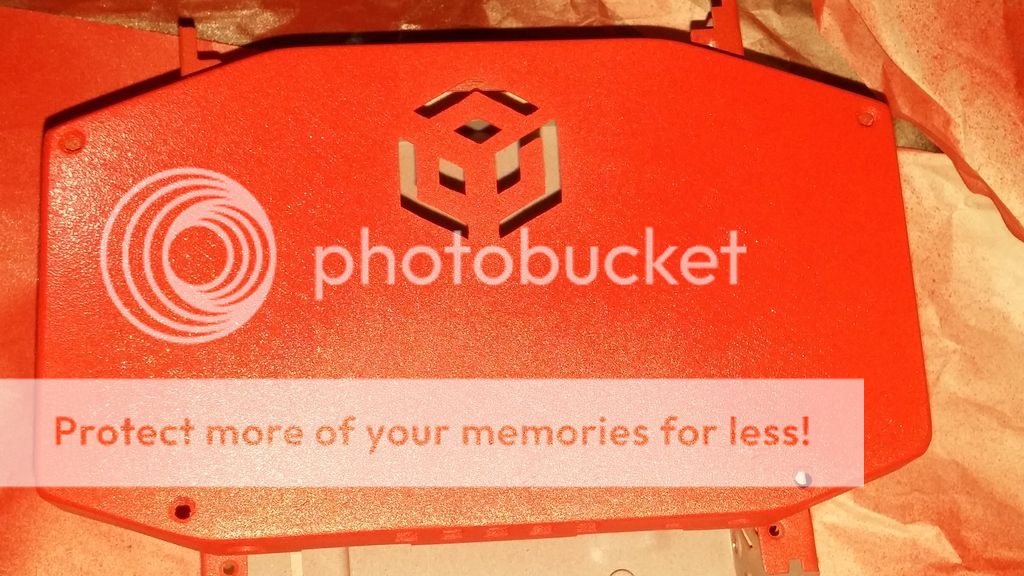
The pictures don't really do the color justice. It's a darker red than the pictures would suggest. That's all I have for now. I will post updates following next week since I'll be on vacation this week.
 
Unnnh stop it. Screw posts? I wish I could do that. Great work so far, it hits a high level of professionalism.
 
Blargaman91 said:
Unnnh stop it. Screw posts? I wish I could do that. Great work so far, it hits a high level of professionalism.

Thanks a lot man. I really appreciate compliments. I have to say that I honestly love this 3d printer. It really is instrumental in bringing my vision to life. Years of AutoCad experience helps out a lot as well. :lol:

Before getting the printer I always made my screw posts from nylon washers purchased from Lowes. I used a screw tap to thread them and epoxied them into place.
 
Where did the 3D printer come from? Is it it hand-built? I've wanted to look into it but the costs are daunting.
 
Blargaman91 said:
Where did the 3D printer come from? Is it it hand-built? I've wanted to look into it but the costs are daunting.

Yeah I know what you mean, the prices of them scare me too. Plus the cost of the plastic and then if you make mistakes you are pretty much just throwing away wasted material that is no good anymore.
 
Blargaman91 said:
Where did the 3D printer come from? Is it it hand-built? I've wanted to look into it but the costs are daunting.

I actually found the price to be quite reasonable actually. The one I bought was on sale for $400. It's a Xyz Davinci 1.0A. I find that it does a very good job, especially for the price. Building one would cost around the same amount too.

thatguythere said:
Yeah I know what you mean, the prices of them scare me too. Plus the cost of the plastic and then if you make mistakes you are pretty much just throwing away wasted material that is no good anymore.

My printer uses Cartridges that are $30 each. Filament rolls only cost $15. I've already printed 3 cases out with my red cartridge and I still have enough filament left for one more case. If you factor in the cost of epoxy, bondo and other matierials and tools that you need to make a proper case it adds up to be much more than even a cartridge of filament costs. It's an investment that saves you money in the end.
 
What the Heck, man. Screw posts? Cavities for the heatsink, batteries, and screen? Pofessional level CAD work? How are we supposed to compete with this?
 
Thank you guys for the kind words.

The screen is 5.6" actually. I'm looking forward to showing you guys some more progress. If anyone has any questions to how I do any of three stuff in this work log, feelfree to ask. I don't mind helping at all.
 
Nice to see some fellow 3D printer-ers here. Did you print in ABS or PLA?

One thing I'd recommend looking into is brass knurles for the screw posts. I've always had a problem with screw posts de-laminating or stripping.

http://www.mcmaster.com/#brass-inserts/=xxr21a

They're what are used in laptops for the screw posts. Normally they use microwaves to heat the metal and melt into the plastic but you can push them in with a soldering iron as well.
 
Thanks for the tip Bentomo, I'll definitely keep it in mind. I'm using ABS right now.

Sent from my VS985 4G using Tapatalk
 
Update 7/12/15

Alright guys, I have an update for you all. I have begun fitting and wiring the parts into the bottom portion of the case. I've also put together another pair of my double tact modded shoulder buttons and mounted them. When I assemble a portable, I use a layering method. I find it to be much easier this way for many reasons. It is easier to keep track of everything making it difficult to get the wiring wrong, it is easier to wire everything neatly primarily by cutting your wires to length and it makes it easier to test things since all the components are mounted securely and safely in place.


Below is a picture of the completed 1st layer of the bottom portion of the portable.


Here's a picture of both tact switches, one hard and one soft, mounted on a breadboard on top of one another.


Underside of the breadboard


A picture of the button disassembled and cut to fit the new double tact breadboard


Here's a picture of the button assembled, mounted and epoxied in the case.
 
Update 7/13/15:


I did as much of the first layer as I could in the top half of the case. I would have had the screen mounted had that seller not sent me the wrong size screen by mistake... Waiting for the replacement screen to come in is gonna cost me some time on this project, but hopefully I can progress to where the only thing I need to do is install the screen.

Here's a picture of layer 1 of both halves wired up.


Here's the first picture of the test fit I did with both halves together. You can see that all the controls are mounted in place.


Here's the second picture at an angle.


That's all for now.
 
I agree with the layered approach. It definitely helps to make things smoother. As for your portable, wow! Nicely done!

I considered buying the xyz Divinci 1.0A last year when they were on sale but never did unfortunately. If you could go back, would you buy it again or go with another type? Again nicely done!
 
stuckonarock said:
I agree with the layered approach. It definitely helps to make things smoother. As for your portable, wow! Nicely done!

I considered buying the xyz Divinci 1.0A last year when they were on sale but never did unfortunately. If you could go back, would you buy it again or go with another type? Again nicely done!

Thank you. I have to say that I am very happy with the Davinci 1.0A. However, there were two things that I did not like about it.

1) Calibrating it is a huge pain and a tedious process.
2) The proprietary software that it ships with is horrible. Luckily, this can be remedied by either flashing the printer with a custom rom or by purchasing Simplify 3d. I chose the latter.

thatguythere said:
Wow it looks so neat in there. Nice work!

Thank you. Like they say, "A place for everything and everything in it's place."

bentomo said:
Looks awesome!

Are you going to strip down another gc hd cable or do the cable clone?

Thank you.

I'm actually going to go with Composite video this time around. The reason is, well frankly, VGA (component) causes unnecessary issues. This is due to the fact that the screens do not support 15khz VGA and I can't find one that does anymore. The Dalian Good displays used to, but not anymore. Since they don't support 15khz VGA, the main menu looks garbled and off center. Also, games that don't support 480p and cannot be forced into 480p either suffer from the same issue.

Here's a picture of what I mean.
 
Aren't there screens that size that use DVI? That would be compatible with the FPGA alternative to the component cable, I think.
 
Blargaman91 said:
Aren't there screens that size that use DVI? That would be compatible with the FPGA alternative to the component cable, I think.
Unfortunately, there are none that I could find. The only screens I can find with DVI are 16:9.

Also, I'm not so sure that would work unless the FPGA also up scales 480i to 480p.
 
Update 7/15/15

I started and completed layer 2 on the bottom half of the portable today. I trimmed the motherboard, mounted the heat sink and wired up the power, video, audio and ground. For this build, I decided to do a medium trim board cut. I chose this cut because I have enough room inside the case to fit it, and it will save me some time when wiring up the Wasp, Memory Card and SD Gecko. Sure, I could have done an OMGWTF cut, but there was kind of no point to me doing that with all things considered.

This is a picture of the motherboard set and wired into place.


Same as above, but at a different angle.


Here's a picture with the top half on. I took this close up of the right hand side so you guys can see the clearance space I have.


Same as above, but on the left side.


Here's a picture of my test fitting the top and bottom halves together. I also tested the audio and video and everything is working perfectly. Thumbs up!
 
Back
Top