bentomo
Frequent Poster
This is not a guide, just a few things I'd like to point out about the gamecube controller.
One of the most annoying things about gamecube modding is the controller pinout, so I experimented with a controller with my on my phoenix and figured out what you need for portable functionality.
This picture is from kasars guide, you can look at his guide to figure out where they all connect on your gamecube.
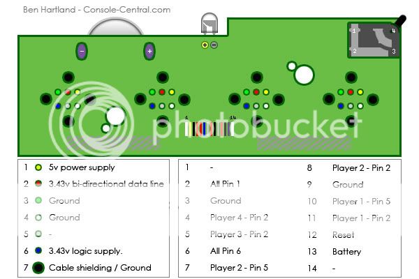
pin 1 - This is the 5v power supply line for rumble. It takes the voltage straight up, you can connect it directly from a regulator no problem. You can use 3.4v from other lines but it is weaker on the default rumble motor, you just need to use a different motor if you want it stronger.
pin 2 - This is the main data line of a gamecube controller it is absolutely necessary for official controller use, however, a wavebird will not function on this pin alone. Each player has its own individual data line, all the other pins are bridged along every controller port, so if you are using other controller ports, this is the only one that needs traced to 4 different spots on the gamecube.
pin 3 - Ground
pin 4 - Ground, you need to bridge both grounds for rumble to work, but you only need pin 3 if you're using a single controller
pin 5 - Completely unused pin, nintendo probably had plans for it but didn't end up using it.
pin 6 -This is another data pin, so far the only thing I can tell that needs it is the wavebird, it's common along all controllers so best just to reconnect just in case.
SonyQrio has found that pin 6 actually just needs 3.34v power, there's no logic involved whatsoever, so just connect it to the power supply.
My theory is it's just extra power for things such as the wavebird.
So using an official controller you only need these combination of wires
Complete functionality -
4 wires
Ground - bridged to pin 3 and 4
Main data line - pin 2 (for that specific controller, player 1, 2, 3, or 4)
5v for rumble - pin 3 (or other voltages depending on what motor you use)
secondary data line - pin 6 (I strongly recommend always connecting this line, its not always necessary but I'm not sure if it's always used)
No rumble, no wavebird, just basic official controller -
3 wires
main data line
ground
pin 6, main power line
So that's basically what I've figured out so far. If you want other controller support like I usually use, you only need 1 extra wire for complete functionality vs an n64, that being the 6th pin, the secondary data line, as the the 3 other lines are common among all the controller.
Any corrections would be helpful, and I'd like to know what that 6th pin is really for.
One of the most annoying things about gamecube modding is the controller pinout, so I experimented with a controller with my on my phoenix and figured out what you need for portable functionality.
This picture is from kasars guide, you can look at his guide to figure out where they all connect on your gamecube.
pin 1 - This is the 5v power supply line for rumble. It takes the voltage straight up, you can connect it directly from a regulator no problem. You can use 3.4v from other lines but it is weaker on the default rumble motor, you just need to use a different motor if you want it stronger.
pin 2 - This is the main data line of a gamecube controller it is absolutely necessary for official controller use, however, a wavebird will not function on this pin alone. Each player has its own individual data line, all the other pins are bridged along every controller port, so if you are using other controller ports, this is the only one that needs traced to 4 different spots on the gamecube.
pin 3 - Ground
pin 4 - Ground, you need to bridge both grounds for rumble to work, but you only need pin 3 if you're using a single controller
pin 5 - Completely unused pin, nintendo probably had plans for it but didn't end up using it.
pin 6 -This is another data pin, so far the only thing I can tell that needs it is the wavebird, it's common along all controllers so best just to reconnect just in case.
SonyQrio has found that pin 6 actually just needs 3.34v power, there's no logic involved whatsoever, so just connect it to the power supply.
My theory is it's just extra power for things such as the wavebird.
So using an official controller you only need these combination of wires
Complete functionality -
4 wires
Ground - bridged to pin 3 and 4
Main data line - pin 2 (for that specific controller, player 1, 2, 3, or 4)
5v for rumble - pin 3 (or other voltages depending on what motor you use)
secondary data line - pin 6 (I strongly recommend always connecting this line, its not always necessary but I'm not sure if it's always used)
No rumble, no wavebird, just basic official controller -
3 wires
main data line
ground
pin 6, main power line
So that's basically what I've figured out so far. If you want other controller support like I usually use, you only need 1 extra wire for complete functionality vs an n64, that being the 6th pin, the secondary data line, as the the 3 other lines are common among all the controller.
Any corrections would be helpful, and I'd like to know what that 6th pin is really for.