Components
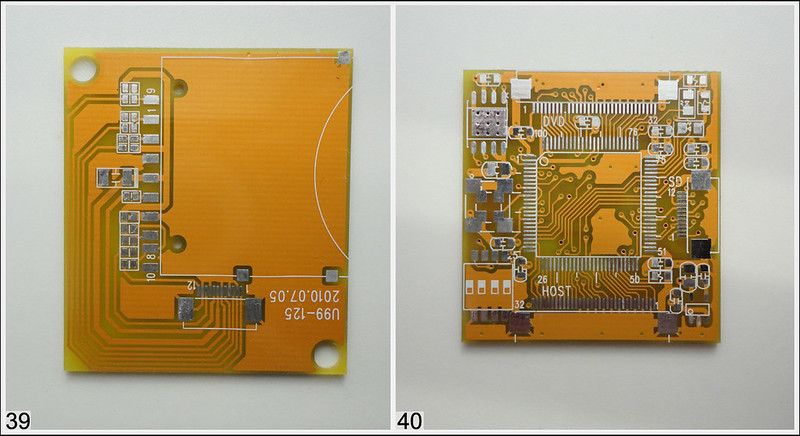
Wasp Fusion
I connect modchip - working good!
Now does not work)
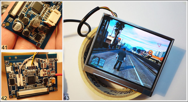
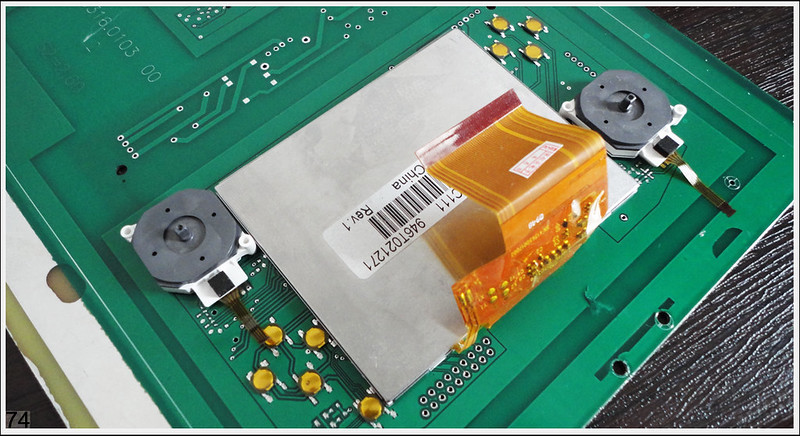
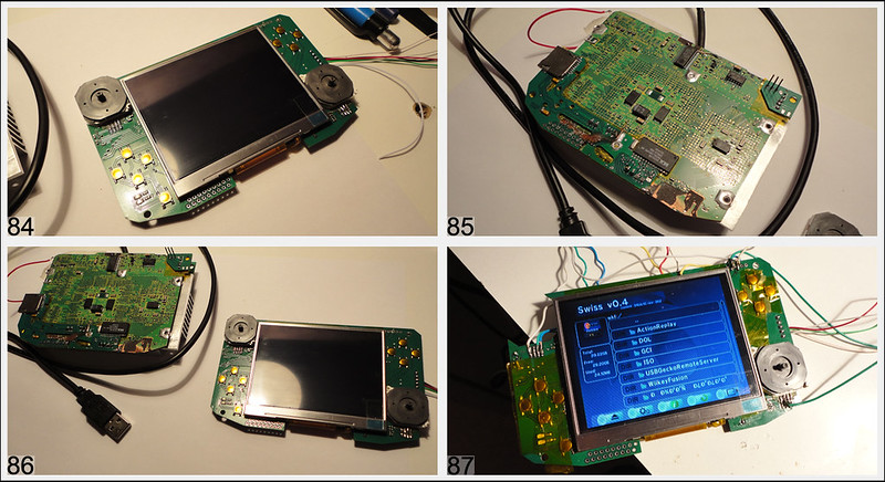
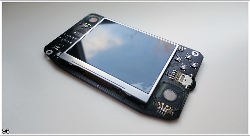
3.5" TFT LCD
I buy 3.5 inch display. I was surprised by his quality. For him test i connect xbox 360 and run gta 5 for 3.5 inch its beautiful. Small pcb on T118 chip, he can work on 480i has av input, svideo input, tv input and another cool hiden opportunity for future upgrades. Lcd - i shocked, so bright so juicy. My camera cant make real color this lcd - hi so bright and camera can't focus on him. Quality better then crt tv on this monitor i can read text! For lcd need 12v but if unsolder step down controller BM1410 (pic.41) and his parts we can use it with 5v. Electrolytic capacitor i change to tantalum capacitor. Quartz and inductor replaced, now he smd type (pic.42)
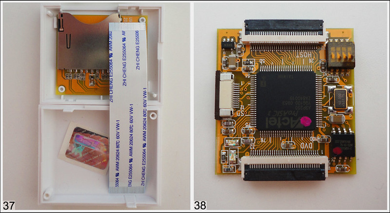
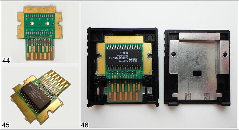
Memory Card
Memcard. I buy 2pc on Ebay. From Japan,) original, was) like new!
Another parts
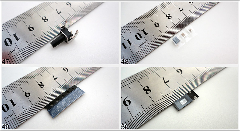
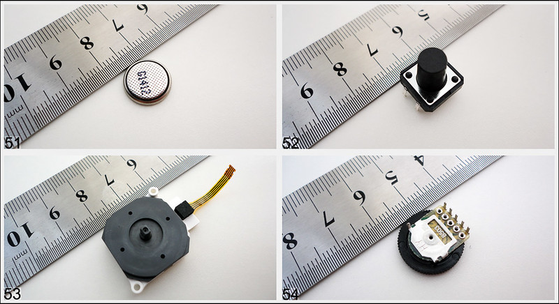
Z-button (pic.47), capacitors, transistor for triggers trick on pic.49 (soon!), new small quartz for tv module.
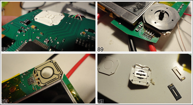
New small battery for bios, buttons for A B X Y on pic.52 (for button trick soon), joystick and potentiometer for amp.
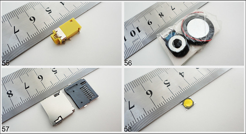
Av output, speakers, microsd card slot for wasp and SD Gecko, smd buttons for button trick will be use on d-pad, start button and A B X Y.
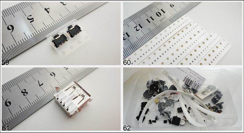
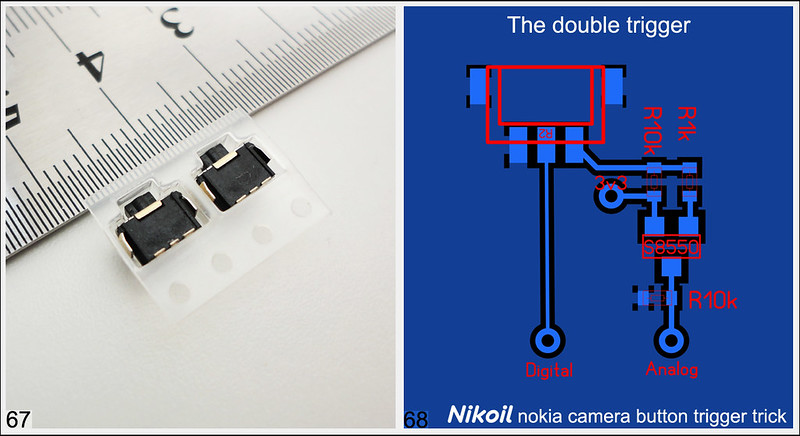
Nokia camera button for trigger, many smd 0402, usb and all together.
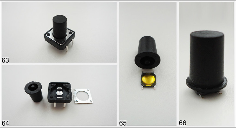
Smd buttons idea pic.63-66
And trigger trick with nokia 2 click camera button for trigger + scheme